
Apparatus and method to optimize sailing efficiency

a technology of optimizing sailing efficiency and optimizing sailing, applied in the field of sailing vessels, can solve the problems of increasing the drag on the hull and keel, reducing the wind speed, and losing forward propelling energy, so as to maximize the efficiency of sailing vessels and optimize sailing efficiency

Inactive Publication Date: 2008-09-11
MAGNASAIL
View PDF13 Cites 13 Cited by
  • Summary
  • Abstract
  • Description
  • Claims
  • Application Information

AI Technical Summary

Benefits of technology

[0039]It is therefore an object of the present invention to provide a drift control and a heel control system that can simultaneously improve leeward drift, heeling, effective weight and associated drag, or any combination thereof, to enable an overall improvement in the efficiency of sailing vessels.

Problems solved by technology

Therefore, directing a vessel at a leeward angle to its track through the water increases the drag on its hull and keel.
Thus, forward propelling energy is lost because less wind energy is captured by the sails.
Unfortunately, what suffers most when the sails are inclined is the production of the upper areas of the sails since they are brought closer to the water surface where, due to wind shear, the wind velocity is lower.
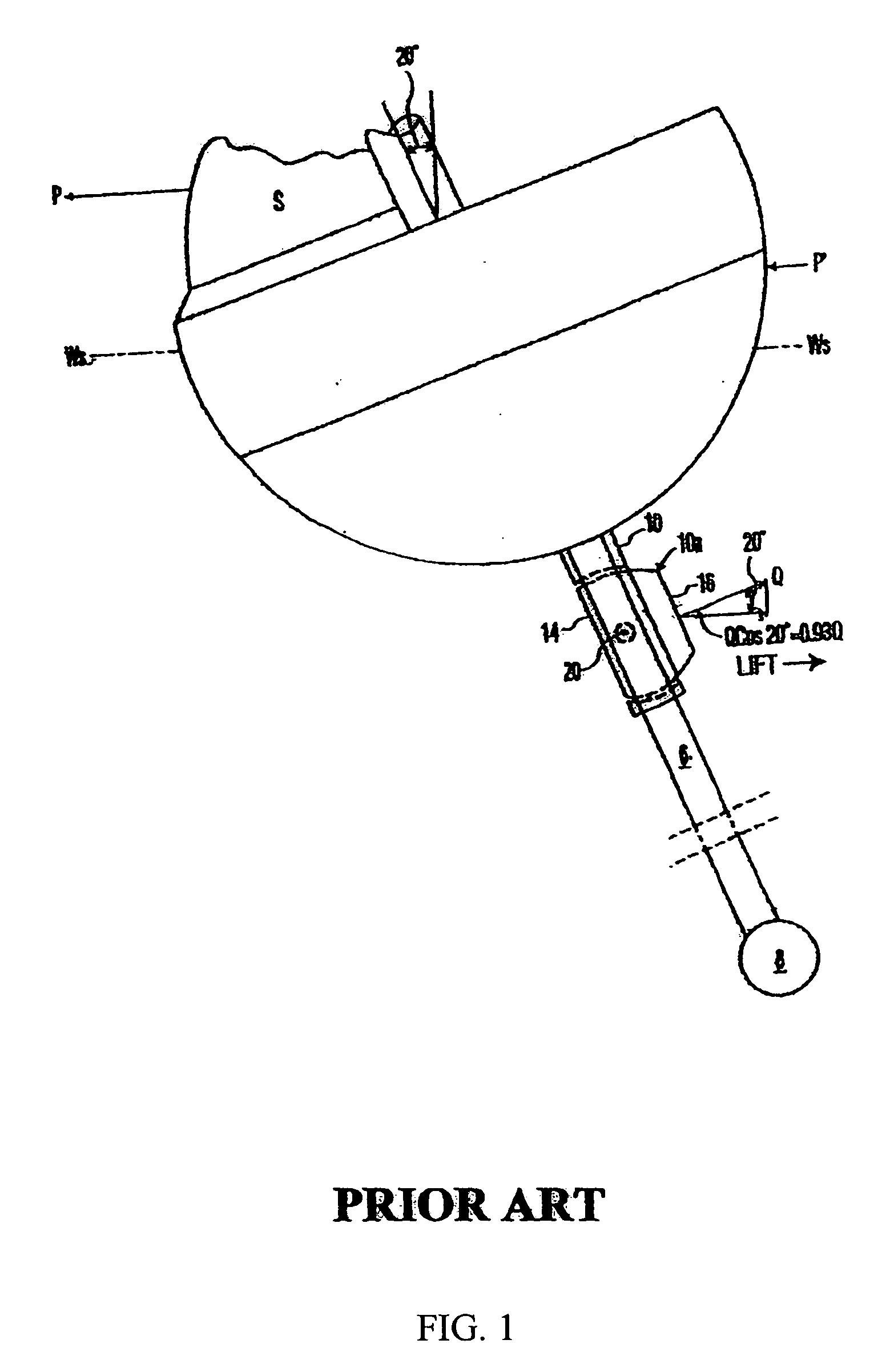
This downward component of the force is lost to forward propelling energy and without compensation would also contribute to the effective weight of the vessel and thereby increase the displacement, wetted surface, and associated drag.
This is not without cost, however, because the higher angle of attack increases the induced drag on the vessel.
For this reason, the drag is also increased by heeling, at an additional expense to the forward velocity of the vessel.
A decrease in the effective weight results in a decrease in the wetted surface and associated drag with an attendant increase in forward velocity.
Less effective weight also improves the vessel's ability to reach a planing condition.
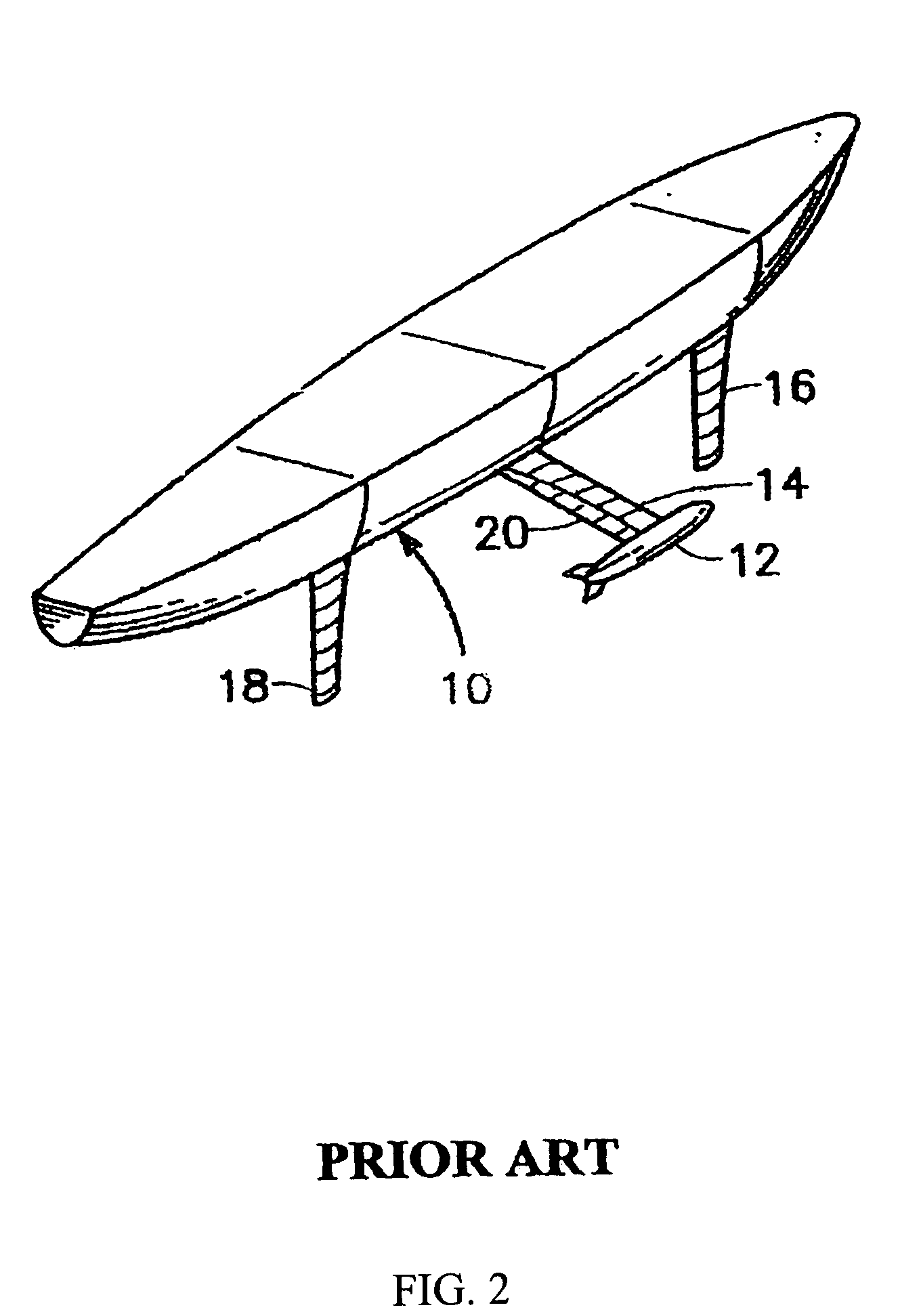
Although efficient in this regard, the horizontal and vertical components of the forces exerted by these hydrofoils, however, either increased the heeling force, or increased the effective weight.
The amount of ballast that is required to provide an adequate amount of counter-heeling moment can add significantly to the weight of the vessel.
Still, such conventional designs afford only limited control of the righting moment and the heeling angle can only be further reduced by lateral motion of the crew or on-board moveable weight.
Such mechanisms do resist heeling moments but, like conventional ballast, because they function gravitationally, considerable weight must be incorporated in their design.
Additionally, a keel canted to a severe angle can do little to resist leeward drift forces.
Such foils, however, produce components that exert significant downward forces on the sailing vessel.
These forces mimic the weight disadvantage of ballast, and tend to pin down or pull the vessel deeper into the water, increasing the displacement, the wetted surface, and the attendant drag, all of which tax the velocity of the vessel.
In addition, depending upon the attitude, shape or efficiency of the hydrofoil, these forces may create significant additional heeling moments proportional to the amount of leeway that the vessel is making.
Still, other prior art keel designs that generate counter-heeling moments either have no compensation on the keel for the drift forces that are necessarily introduced by such counter-heeling designs, or additional appendages are added elsewhere on the hull to counter the drift forces.
If such compensation is provided by a single counter-leeward drift appendage, not in line with the keel, it will likely establish a yawing moment that can reduce the efficiency of the vessel and compromise the rudder's ability to control the vessel.
Two such appendages working to compensate for said counter-heeling device could be added to the hull to provide counter-leeway drift forces and yawing control but likely would add complexity to the system and drag to the vessel.

Method used


Image

  • Apparatus and method to optimize sailing efficiency
  • Apparatus and method to optimize sailing efficiency
  • Apparatus and method to optimize sailing efficiency

Examples


Embodiment Construction

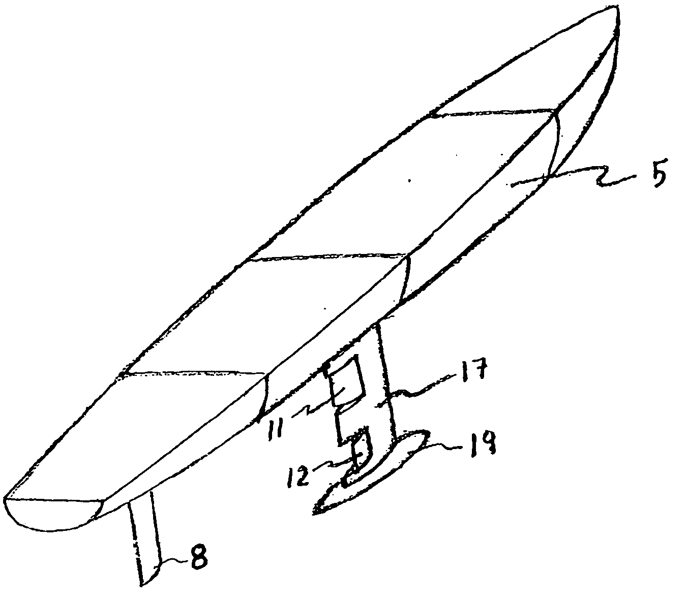
[0149]Turning now more particularly to the drawings, wherein like numbers refer to like elements, characteristics of the present invention are shown in FIGS. 5-18, with particular emphasis on the twin hydrofoil keel mounted combination of a counter-leeward drift hydrofoil acting in concert with a counter-heeling hydrofoil.

[0150]It is understood and defined as used herein that when a flap is hinge-mounted on the keel or similar appendage of a sailing vessel, the flap and the neighboring keel section act in conjunction with each other as a hydrofoil. When the flap is rotated, the overall camber of the hydrofoil changes, thereby changing its hydrodynamic characteristics. Therefore, the forces that are cited herein, in connection with a hinged-flap, are to be considered as the forces that act on the flap as part of the hydrofoil combination of the flap and related keel section.

[0151]The effectiveness of hydrofoils in the production of lift becomes apparent when we consider that the forc...


PUM


Abstract

This invention provides improvements in the efficiency of a sailing vessel through the use of flaps, hydrofoils, or members on the keel of a sailing vessel. One or more are positioned at the top, or root of the keel of the vessel, which primarily generate a force in the windward direction to provide a counter-leeward drift force. One or more are located at the bottom, or tip of the keel of the vessel, which primarily generate a force in the leeward direction to provide a counter-heeling moment. Among other benefits, operation of these flaps, hydrofoils, or members during sailing increases the vessel's efficiency, in particular its velocity made good. Further, since they are mounted on one appendage, sailing vessels of a rudder and keel design can be equipped with counter leeward-drift and counter-heeling attributes without the need for additional appendages.

Description

FIELD OF THE INVENTION[0001]This invention relates to sailing vessels. In particular this invention relates to appendages extending from a sailing vessel hull-keels, centerboards, dagger boards, and the like. More particularly, this invention relates to sailing vessel appendages that simultaneously control leeward drift forces, heeling forces, effective weight, and drag. Although adaptable to sailing vessels of all types, the invention is particularly suited for high performance sailing yachts.BACKGROUND OF THE INVENTION[0002]The time required to reach a windward mark on a passage of a sailing yacht is dependent upon the Velocity Made Good (VMG) which, among other things, is greatly influenced by four major factors: the amount of leeward drift of the vessel, the heeling angle of the vessel, the effective weight of the vessel, and the drag on the vessel.[0003]Velocity Made Good (VMG) is defined as that component of a sailing vessel's velocity made good toward windward. It is that com...

Claims


Application Information

Patent Timeline
IPC IPC(8): B63B1/00
CPCB63B1/286G05D1/0875B63B41/00B63B39/06B63B2003/385
Inventor HOFBAUER, THOMAS J.
Owner MAGNASAIL
Learn More