Operation support system, component arrangement recognition method and cassette arrangement recognition method in component mounting apparatus

a technology of component mounting and recognition method, which is applied in the direction of instruments, computing, electric digital data processing, etc., can solve the problems of increasing man-hours, manufacturing line shutdown, and components contained in reels being erroneously mounted on printed boards, so as to eliminate erroneous mounting, eliminate erroneous mounting of components, and improve operational efficiency and workability

Inactive Publication Date: 2008-09-11
FUJITSU LTD
View PDF8 Cites 30 Cited by
  • Summary
  • Abstract
  • Description
  • Claims
  • Application Information

AI Technical Summary

Benefits of technology

[0034]In the component mounting apparatus of the first or second embodiment of the present invention, because the cassettes and the reels are recognized in a state in which the reels containing the components are loaded on the cassettes, the reel positions in the cassettes, and thus, the components can be properly recognized and, therefore, it is possible to mount the properly recognized components on the intended printed boards and eliminate erroneous mounting.
[0035]More specifically, after the reels containing the components are loaded on the cassettes, the data recorded in the bar codes stuck on the reels or the wireless IC tags incorporated into the reels is read out to recognize the cassettes and the reels and, therefore, the reel positions in the cassettes, and thus, the components can be properly recognized.
[0036]Further, in the component mounting apparatus of the first or second embodiment, when a plurality of different types of the components are accommodated in one cassette, the information of the different types of the components is recorded on each reel in the one identical cassette, and therefore, the reel positions in the cassettes, and thus, the components can be properly recognized, and further, it is possible to eliminate erroneous mounting of the components on the intended printed boards due to downsizing of the cassettes as a result of downsizing of the component mounting apparatus.
[0037]Still further, even if the actual mounter on the manufacturing line is operating, it can be checked where the components are loaded in the cassettes at a location remote from the manufacturing line, and therefore, operational efficiency and workability can be improved.
[0038]In the operation support system of third, fourth or fifth embodiment of the present invention, because the cassette loading checking section moves by itself to read out the cassette identification information for identifying the cassettes loaded on a plurality of lanes, obtains the identification information of the components loaded on the cassettes from the cassette identification information, and determines whether the cassette loading positions in the carts are correct or not by comparing the obtained component identification information with the previously set information for specifying the cassette loading positions in the carts, the cassette loading positions in the carts can be properly recognized, and therefore, operating time for loading the cassettes on the lanes in the carts can be reduced and workability can be improved. Further, there is an effect that the components contained in the cassettes loaded on the cassettes can be properly recognized, and therefore, the erroneous mounting of the components on the intended printed boards due to erroneous operation when the cassettes are loaded on the lanes can be avoided.
[0039]Further, in the operation support system of third, fourth or fifth embodiment, by configuring said reading section, for example, the antenna to be self-propelled, the need to provide a plurality of reading sections (antennas) receiving the cassette identification information corresponding to the number of cassettes loaded on the carts can be eliminated and an inexpensive operation support system can be implemented.

Problems solved by technology

In the mounter, there occur various problems such as an increase in man-hours, occurrence of defectives due to erroneous operation, manufacturing line shutdown for long hours and so on.
The cassettes of (1) have a problem in that, if the reel loading positions in the cassettes are erroneously recognized, the components contained in the reels will be erroneously mounted on the printed boards.
The carts of (2) have a problem in that, if the cassette loading positions in the carts are erroneously recognized, the components contained in the cassettes loaded on the carts will be erroneously mounted on the printed boards.
In the component management system intended for the printed board mounting system as set forth in Patent Document 1, after the component reels 36 are loaded on cassettes 21, the cassettes 21 may be accommodated in improper lane positions among the plurality of lanes Z1-Zn in the mounter 20 due to erroneous operation, and in this case, there is a problem in that the mounter 20 cannot attach the component to proper positions on the printed boards or in other words, erroneous mounting will occur and faulty printed board units will be manufactured.
The pallet organization system as set forth in Patent Document 2 has a problem in that, when the pallets 36 are carried to the small-sized component mounting machine 15 by the self-propelled wagons 26, which cartridges 35 are loaded on which channels of the pallets 36 by manually or bar code verification, is verified and therefore, it takes considerable time.
Further, when the carts are set in the mounter from which a plurality of carts can be detached, there is also a problem in that, if the plurality of carts are set in improper positions of the mounter, the components will be erroneously mounted on the printed boards.

Method used


Image

  • Operation support system, component arrangement recognition method and cassette arrangement recognition method in component mounting apparatus
  • Operation support system, component arrangement recognition method and cassette arrangement recognition method in component mounting apparatus
  • Operation support system, component arrangement recognition method and cassette arrangement recognition method in component mounting apparatus

Examples


Embodiment Construction

[0073]Hereinafter, the embodiments of the present invention will be described with reference to the drawings.

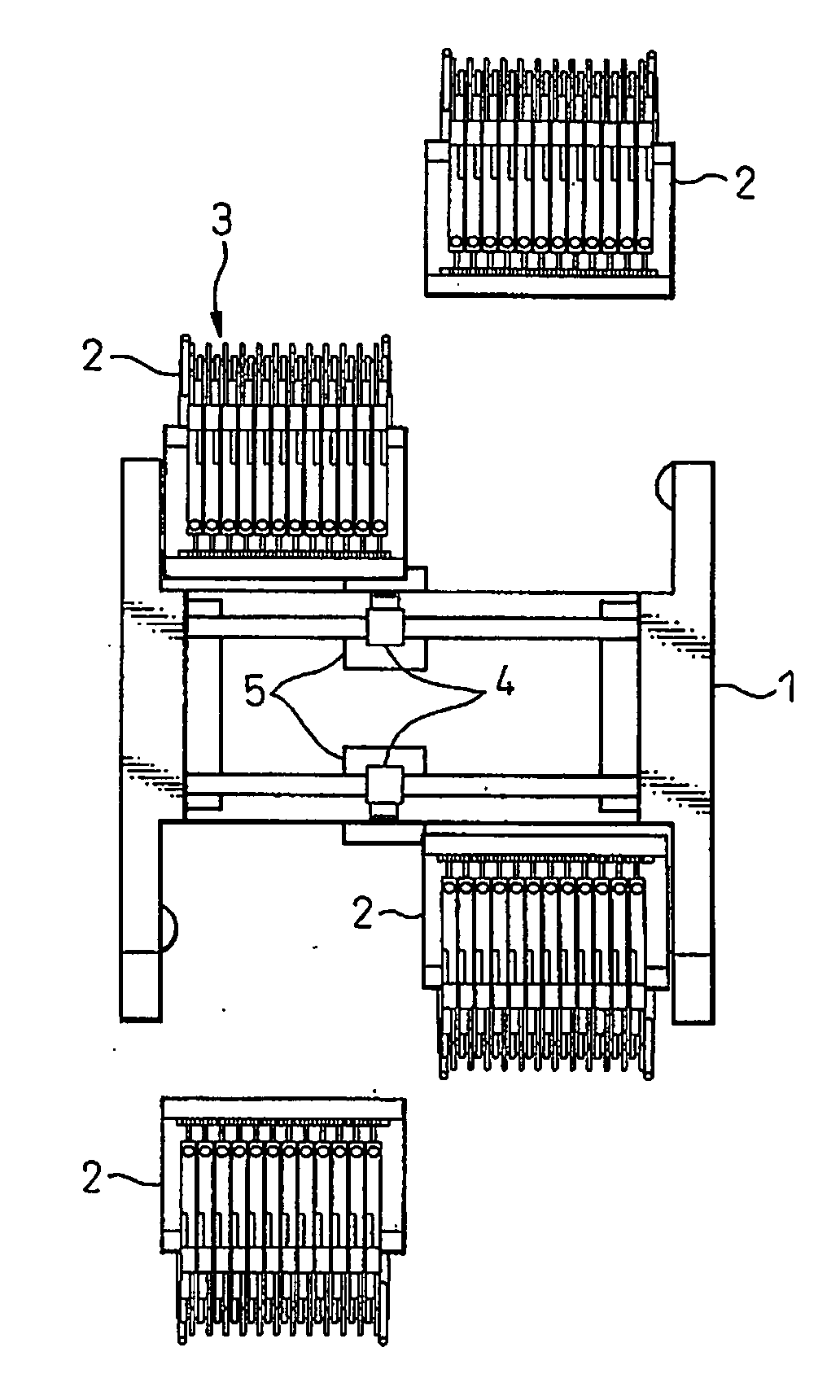
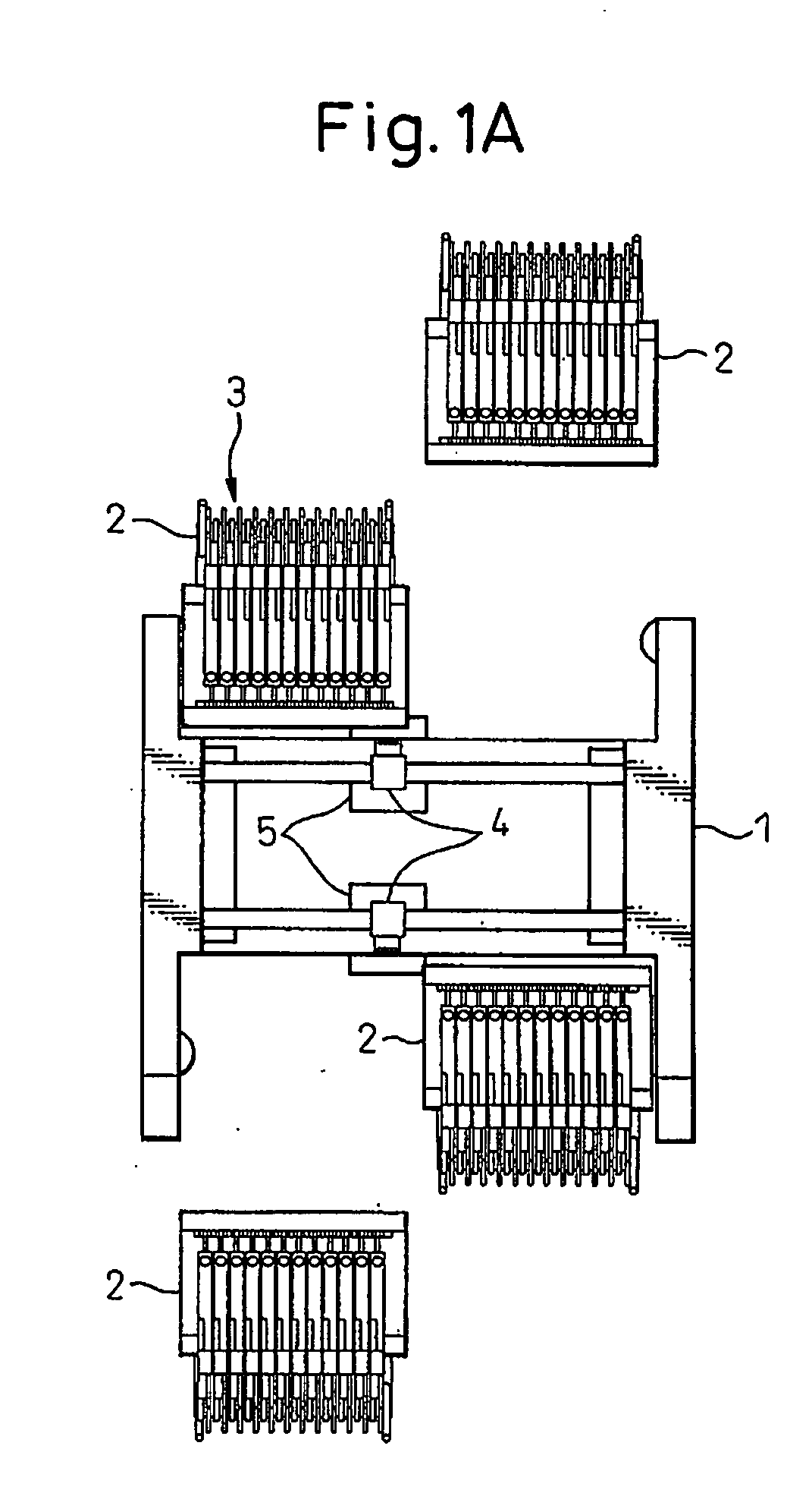
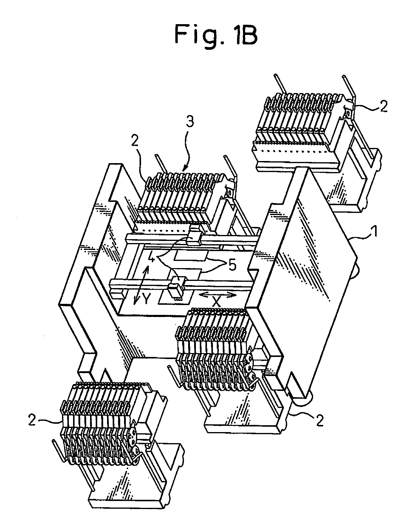
[0074]FIGS. 1A and 1B are diagrams showing a printed board component mounting apparatus according to an embodiment of the present invention, wherein FIG. 1A is a plan view and FIG. 1B is a perspective view. As shown in FIGS. 1A and 1B, four carts 2 can be removably loaded on a printed board component mounting apparatus (mounter) 1 that is installed on a manufacturing line for manufacturing printed board units where components are incorporated into printed boards. A plurality of cassettes 3 can be loaded on each cart 2. Two nozzles 4 are attached to the mounter 1 movably in two-axis directions along the X and Y axes, so that each nozzle 4 sucks components that are wound around reels (see FIGS. 2 and 3) in the cassettes 3 and carries it onto printed boards 5 that are located below the nozzle 4 to place the components at desired positions on the printed boards 5.

[0075]FIG. 2 is ...


PUM


Abstract

An operation support system in a component mounting apparatus on a manufacturing line for manufacturing printed board units, comprises: an ID reading unit that reads out cassette identification information for identifying cassettes and component identification information for identifying components from the cassette each comprising tags for recording the cassette identification information and tags for recording the component identification information, wherein at least one reels are loaded on each cassette and tapes to which the components are attached are wound around the reels, and the components are contained in the reels accommodated in the cassettes; a storage unit that stores information for specifying the components previously set to be loaded on the cassettes; and a component loading checking unit that checks whether or not the components loaded on the cassettes are correct by comparing the component identification information with the specifying information corresponding to the cassette identification information.

Description

CROSS-REFERENCE TO RELATED APPLICATION[0001]This application is a continuation application and is based upon PCT / JP2005 / 021288, filed on Nov. 18, 2005.TECHNICAL FIELD[0002]The present invention relates to an operation support system, a component loading state recognition method and a cassette loading state recognition method in a component mounting apparatus, and specifically, it relates to an operation support system, a method for recognizing a component loading state in cassettes on which components are loaded and a method for recognizing a cassette loading state in carts on which the cassettes are loaded in a printed board component mounting apparatus that is provided on a manufacturing line for manufacturing printed board units in which the components are incorporated into printed boards and that mounts the components on the printed boards.BACKGROUND ART[0003]Patent Document 1 describes a component management apparatus intended for a printed board mounting system. As shown in FI...

Claims


Application Information

Patent Timeline
Patent Type & Authority Applications(United States)
IPC IPC(8): G06F17/00
CPCH05K13/0417H05K13/08H05K13/0452H05K13/086
Inventor OKADA, HIROYUKIIIDA, MITSUHIROMATSUMOTO, SHIGEJIROU
Owner FUJITSU LTD
Why Eureka
Try Eureka