Content-Dependent Scan Rate Converter with Adaptive Noise Reduction

a conversion rate and scan rate technology, applied in the field of scan rate conversion, can solve the problems of blurring the high spatial detail of the image, the inability to use information from the previous interlaced field, and the noise on the video to be considered, so as to achieve high integration, adaptive noise reduction, and high efficiency of implementation

Inactive Publication Date: 2008-09-11
TEXAS INSTR INC
View PDF10 Cites 36 Cited by
  • Summary
  • Abstract
  • Description
  • Claims
  • Application Information

AI Technical Summary

Benefits of technology

[0009]The content-dependent scan rate converter with adaptive noise reduction of the present invention is a highly integrated, implementation efficient, de-interlacer. By identifying and using redundant information (motion values and edge directions), this scan rate converter is able to perform the tasks of film-mode detection, motion-adaptive scan rate conversion, and content-dependent video noise reduction, while minimizing the amount of logic needed to perform these tasks.
[0011]However, when the original source is an inherently interlaced signal, then the motion-adaptive scan rate converter must determine how best to combine information from the current interlaced field and the previous interlaced field. The motion-adaptive scan rate conversion process employs an edge-adaptive interpolation technique. In the presence of motion, pixels are interpolated using only the current field. By interpolating along an edge, high vertical detail can be maintained. In the absence of motion, the present field is jammed with the previous field. To prevent false motion detection, the scan rate converter uses a temporal maximum motion filter. Since simple, frame-based motion detection fails when moving objects change direction or move quickly, a temporal maximum motion filter is used to provide a memory of previous locations of moving objects.

Problems solved by technology

But, if motion is detected, information from the previous interlaced field cannot be used.
In addition, noise on the video must be considered in the scan conversion process since it can give a false indication of motion and can also blur the high spatial detail of the image.

Method used


Image

  • Content-Dependent Scan Rate Converter with Adaptive Noise Reduction
  • Content-Dependent Scan Rate Converter with Adaptive Noise Reduction
  • Content-Dependent Scan Rate Converter with Adaptive Noise Reduction

Examples


Embodiment Construction

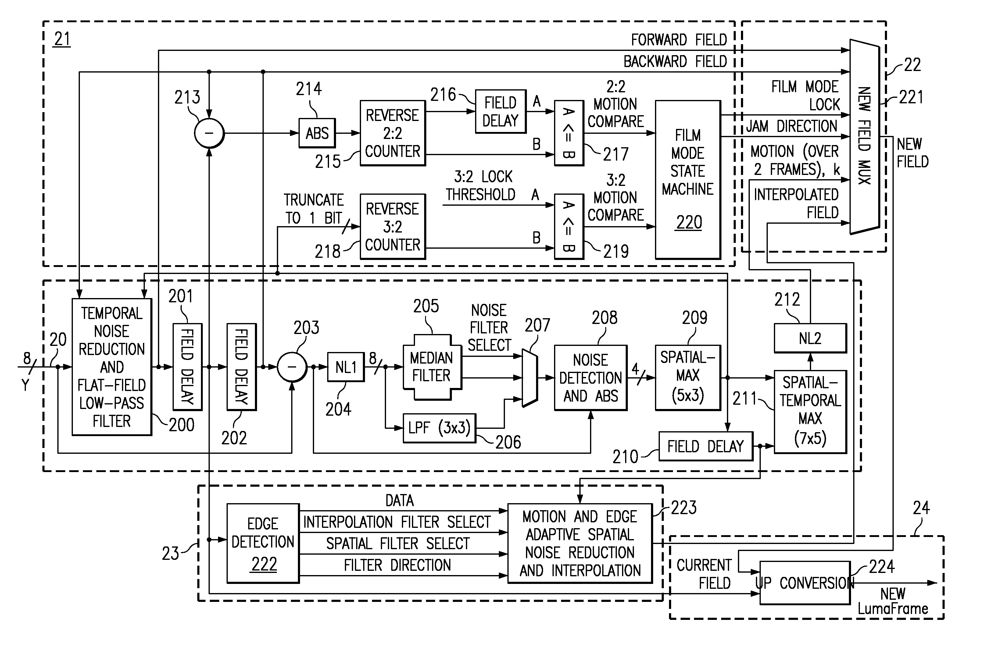
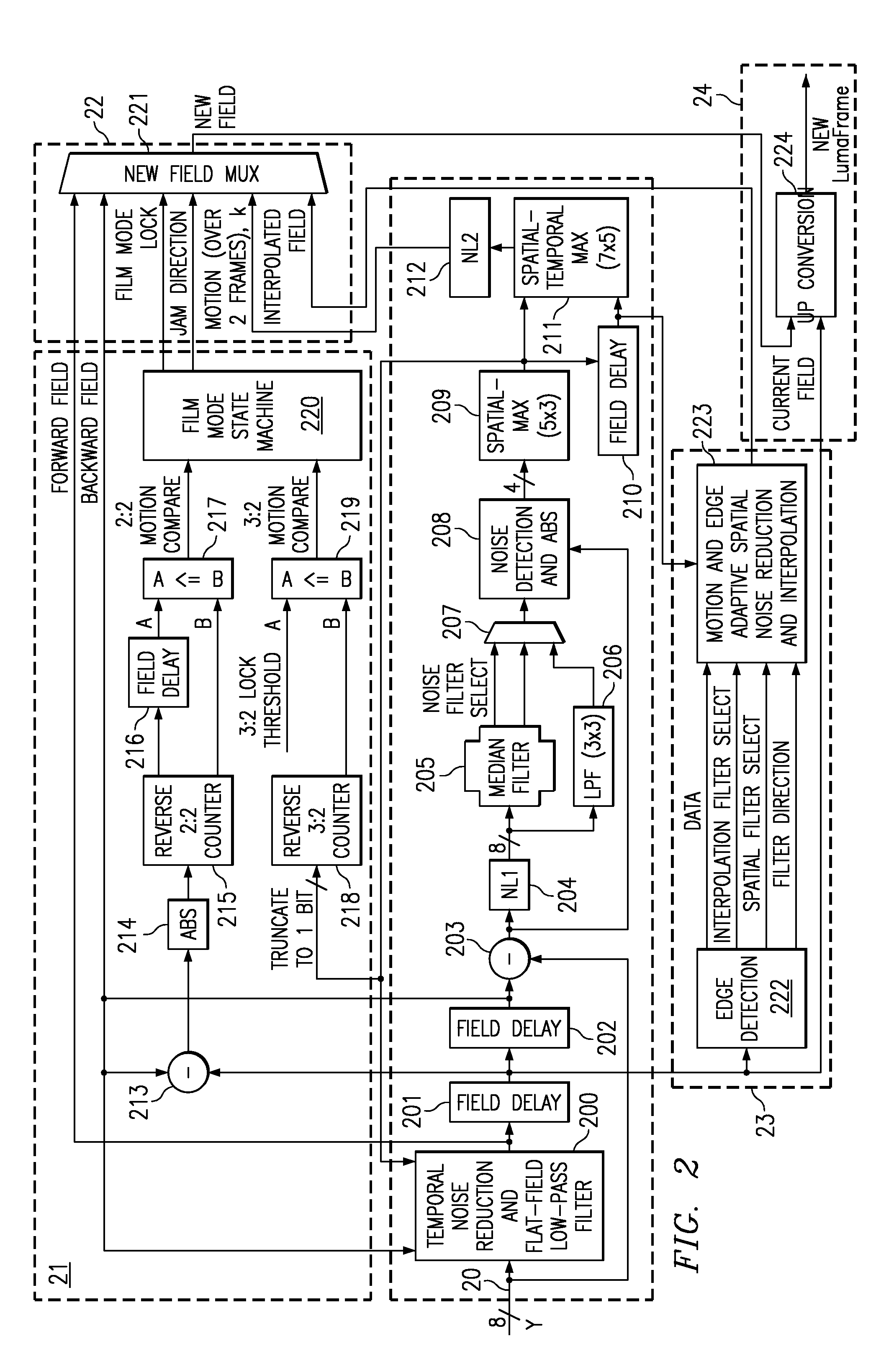
[0040]The content-dependent scan rate converter with adaptive noise reduction of the present invention identifies and uses redundant information (motion values and edge directions) to perform the tasks of film-mode detection, motion-adaptive scan rate conversion, and content-dependent video noise reduction.

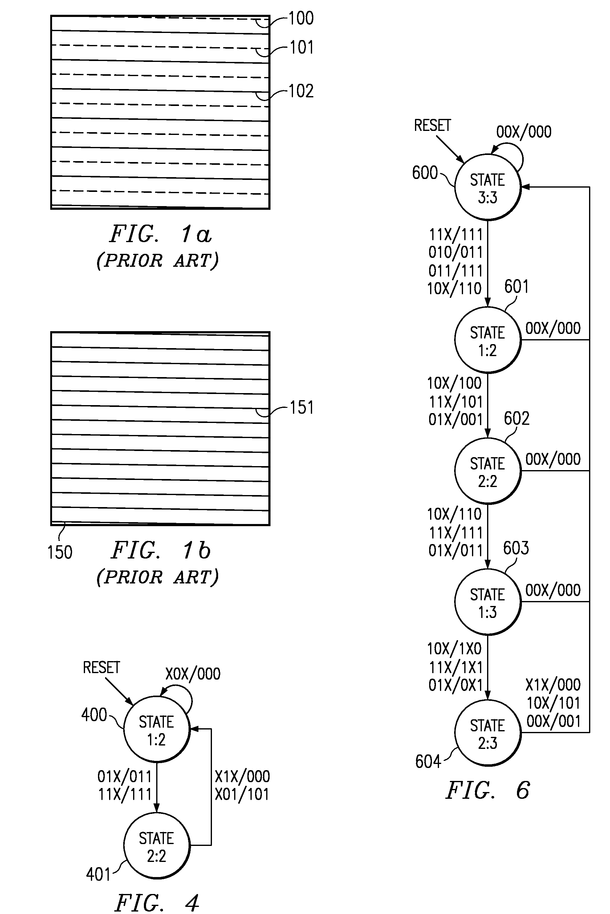
[0041]If the interlaced image sequence is created from a progressive source, such as film, then the progressive frame is created by jamming the appropriate adjacent fields together. Both 3:2 (60 Hz) film mode detection (NTSC) and 2:2 (50 Hz) film mode detection (PAL) are addressed in the method of the present invention. Additionally, when the film source is lost, the method smoothly switches from film mode (field jam) to motion-adaptive scan rate conversion.

[0042]However, when the original source is an inherently interlaced signal, then the motion-adaptive scan rate converter must determine how best to combine information from the current interlaced field and the previous interlac...


PUM


Abstract

A content-dependent scan rate converter with adaptive noise reduction that provides a highly integrated, implementation efficient de-interlacer. By identifying and using redundant information from the image (motion values and edge directions), this scan rate converter is able to perform the tasks of film-mode detection, motion-adaptive scan rate conversion, and content-dependent video noise reduction. Adaptive video noise reduction is incorporated in the process where temporal noise reduction is performed on the still parts of the image, thus preserving high detail spatial information, and data-adaptive spatial noise reduction is performed on the moving parts of the image. A low-pass filter is used in flat fields to smooth out Gaussian noise and a direction-dependent median filter is used in the presence of impulsive noise or an edge. Therefore, the selected spatial filter is optimized for the particular pixel that is being processed to maintain crisp edges.

Description

FIELD OF THE INVENTION[0001]The present invention relates to scan rate conversion and particularly to converting interlace video to progressive video based on the data content.BACKGROUND OF THE INVENTION[0002]Many spatial light modulators (SLMs), such as the digital micro-mirror device (DMD™) are inherently progressive display devices. Therefore, systems built around these devices require scan-rate conversion of their interlaced video signals in order to double the vertical resolution of each image field. FIG. 1a illustrates an interlaced frame 100, which consists of two fields, field A 101 (dotted line) and field B 102 (solid line). For example, in an NTSC signal these field are approximately 16.7 mSec apart in time with the lines from field A 101 being presented on the TV screen and then the lines from field B 102 being inserted between the field A lines, so that two 60 Hz fields are combined to provide a 30 Hz interlaced frame rate. However, in a progressive display system 150, e...

Claims


Application Information

Patent Timeline
Patent Type & Authority Applications(United States)
IPC IPC(8): H04N7/01H04N5/213H04N5/44H04N5/74
CPCH04N5/213H04N5/7416H04N7/0137H04N7/0115H04N7/012H04N5/7458
Inventor KEMPF, JEFFREYSKOOG, ARNOLD P.FAIRBANKS, CLIFFORD D.
Owner TEXAS INSTR INC
Why Eureka
Try Eureka