Led Control Utilizing Dynamic Resistance of Leds
a technology of led control and leds, applied in outdoor lighting, coupling device connections, lighting heating/cooling arrangements, etc., can solve the problems of high maintenance costs, large heat generation, and large use of electricity to produce ligh
- Summary
- Abstract
- Description
- Claims
- Application Information
AI Technical Summary
Benefits of technology
Problems solved by technology
Method used
Image
Examples
first embodiment
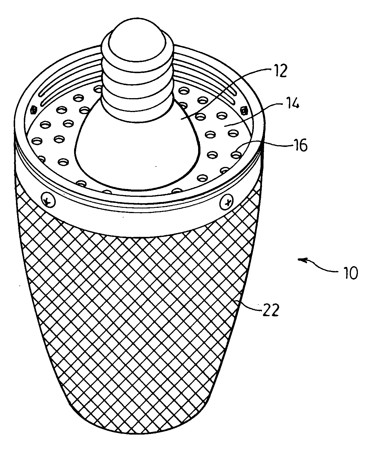
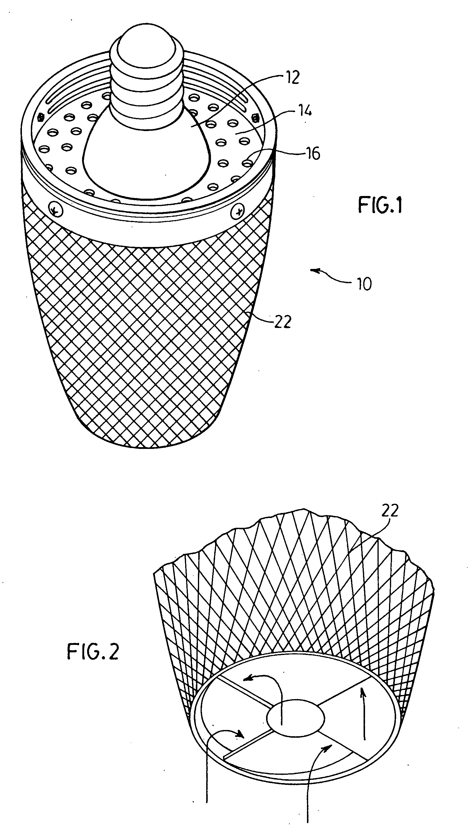
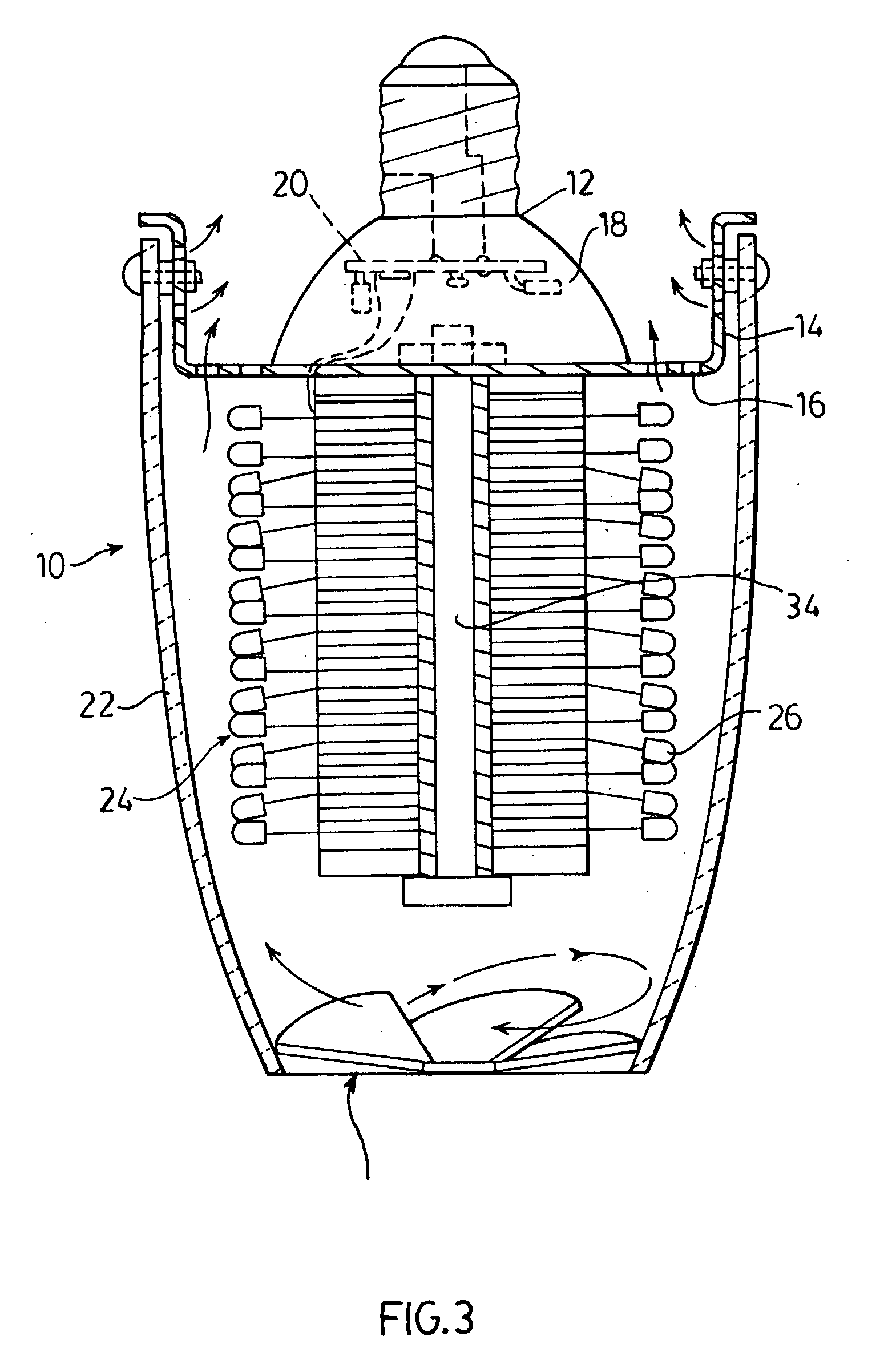
[0037]an LED light fixture of the present invention for use as a replacement for residential incandescent light bulbs is illustrated in FIGS. 1 to 5 generally indicated by the numeral 10. The LED light bulb 10 is provided with a screw base interface 12 which fits into the standard screw base fixtures. The screw base 12 is affixed to a thermal cap 14 containing openings 16 to allow for air flow through the bulb 10 as will be described later.
[0038]The screw base 12 also houses the power / control electronics used for powering the LED bulb array. The screw base 12 is a flanged form with a cavity space 18 that accommodates the power / control circuitry 20. An acrylic frosted diffused lens 22 covers the LED bulb array 24 and is attached to the thermal cap 14.
[0039]The electro / thermal core section 24 makes possible the interconnection of a very high density array of LEDs 26. The core 24 provides electrical interconnection, thermal collection and physical support for the LEDs 26. The heat gene...
third embodiment
[0054]the LED light fixture of the present invention for use in replacement of fluorescent light fixtures as illustrated in FIGS. 9 to 14 generally indicated by the numeral 110. The LED light fixture 110 illustrated in the figures is adapted to be suspended from a ceiling 112. A mounting bracket 114 such as that illustrated in the figures is attached to the ceiling 112 over the electrical outlet box 116. The light fixture 110 is suspended from the bracket 114 through the use of suitable suspension guy wires 118 and is connected to the electrical box 116 by wire 120. Wire 120 is in turn connected to a control box 122 which contains the power control circuitry for supplying and controlling the power to the LED array assembly 124, the details of which will be described further below. The light from the LED array 124 passes through a diffuser system 126 to provide for even and uniform light output from the light fixture.
[0055]The details of the light components of this embodiment are il...
fourth embodiment
[0057]a LED light fixture of the present invention is illustrated in FIG. 15 generally indicated by the numeral 200. This light fixture is provided with an LED array 212 mounted within a housing 214. A diffuser 216 is provided to attach to the housing 214 and hold the components within the housing 214. In order to space the LED array 212 from the diffuser 216, a spacer strip 218 is provided which allows for air flow for cooling of the LED array 212. The LED's are powered by a power / control component 220 connected to an electrical source by wire 222. The embodiment of the invention illustrated in FIG. 15 is particularly useful for strip lighting or replacing fixtures having a single fluorescent tube.
[0058]This embodiment of the LED light fixture of the present invention is of particular use for grow bulbs for use in greenhouses and other such applications. These grow bulbs provide for photosynthetic active radiation (PAR) which typically is light in the wave length range 400 to 525 n...
PUM
 Abstract
Description
Claims
Application Information
 - R&D
- Intellectual Property
- Life Sciences
- Materials
- Tech Scout
- Unparalleled Data Quality
- Higher Quality Content
- 60% Fewer Hallucinations
Browse by: Latest US Patents, China's latest patents, Technical Efficacy Thesaurus, Application Domain, Technology Topic, Popular Technical Reports.
© 2025 PatSnap. All rights reserved.Legal|Privacy policy|Modern Slavery Act Transparency Statement|Sitemap|About US| Contact US: help@patsnap.com


