
System and method for fault detection and localization in time series and spatial data

Active Publication Date: 2008-09-11
GENERAL ELECTRIC CO
View PDF4 Cites 1 Cited by
  • Summary
  • Abstract
  • Description
  • Claims
  • Application Information

AI Technical Summary

Benefits of technology

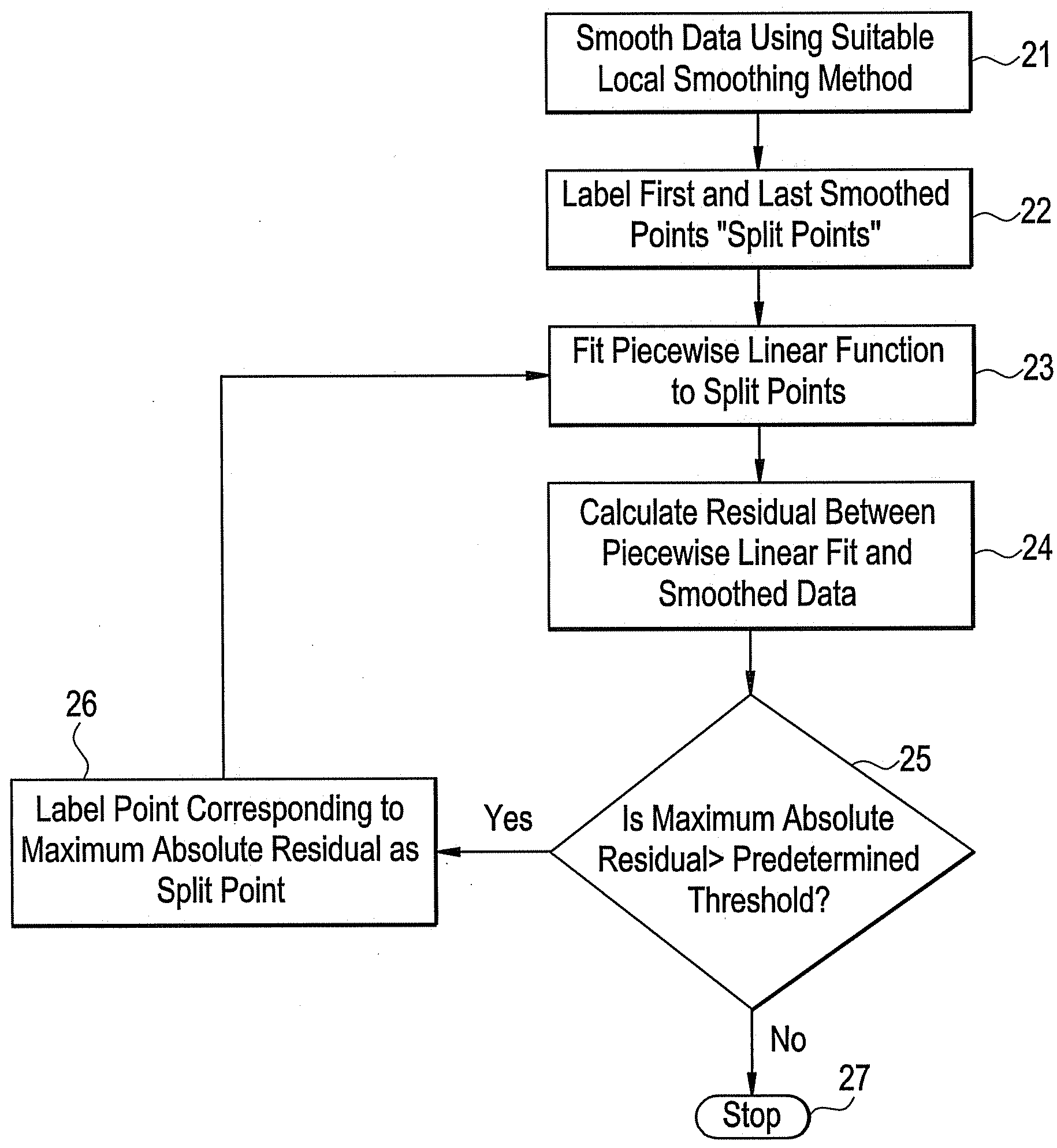
[0008]The invention described herein provides an accurate method for fault detection and localization in time series or spatial data. The invention has been applied successfully to several data sets from different domains. A key feature of this invention is accuracy: it both indicates fewer spurious faults, and indicates the exact point of onset of faults more accurately than other prior art techniques examined.

Problems solved by technology

Abnormal conditions, also known as faults, are the first sign of a potential equipment failure at some future time.
The direct cost of equipment failures is unavoidable: ultimately, the faulted component must be replaced.
However, there are indirect costs to equipment failure that are in many cases far greater than the cost of the repair.
One source of indirect costs is secondary damage (e.g., component failure in the compressor stage of a gas turbine might cause damage to the rear stages).
Another indirect cost is unscheduled maintenance.

Method used


Image

  • System and method for fault detection and localization in time series and spatial data
  • System and method for fault detection and localization in time series and spatial data
  • System and method for fault detection and localization in time series and spatial data

Examples


Embodiment Construction

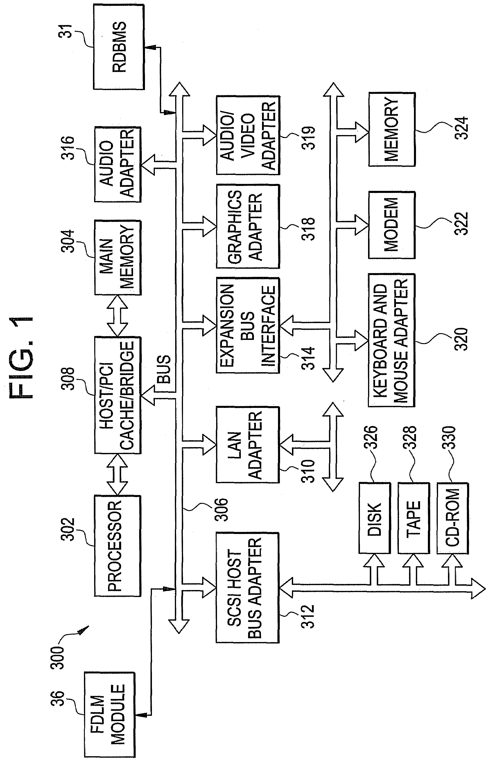
[0024]With reference now to FIG. 1, a block diagram illustrating a fault detection and localization (FDL) system (i.e., a data processing system 300) 300 is depicted. The fault detection and localization (FDL) system 300 may be used for implementation of the teachings herein. In typical embodiments, the FDL system 300 employs a peripheral component interconnect (PCI) local bus architecture. Although the depicted example employs a PCI bus, other bus architectures such as Accelerated Graphics Port (AGP) and Industry Standard Architecture (ISA) may be used. Processor 302 and main memory 304 are connected to PCI local bus 306 through PCI bridge 308. PCI bridge 308 also may include an integrated memory controller and cache memory for processor 302. Additional connections to PCI local bus 306 may be made through direct component interconnection or through add-in boards.

[0025]In the example depicted, local area network (LAN) adapter 310, SCSI host bus adapter 312, and expansion bus interfa...


PUM


Abstract

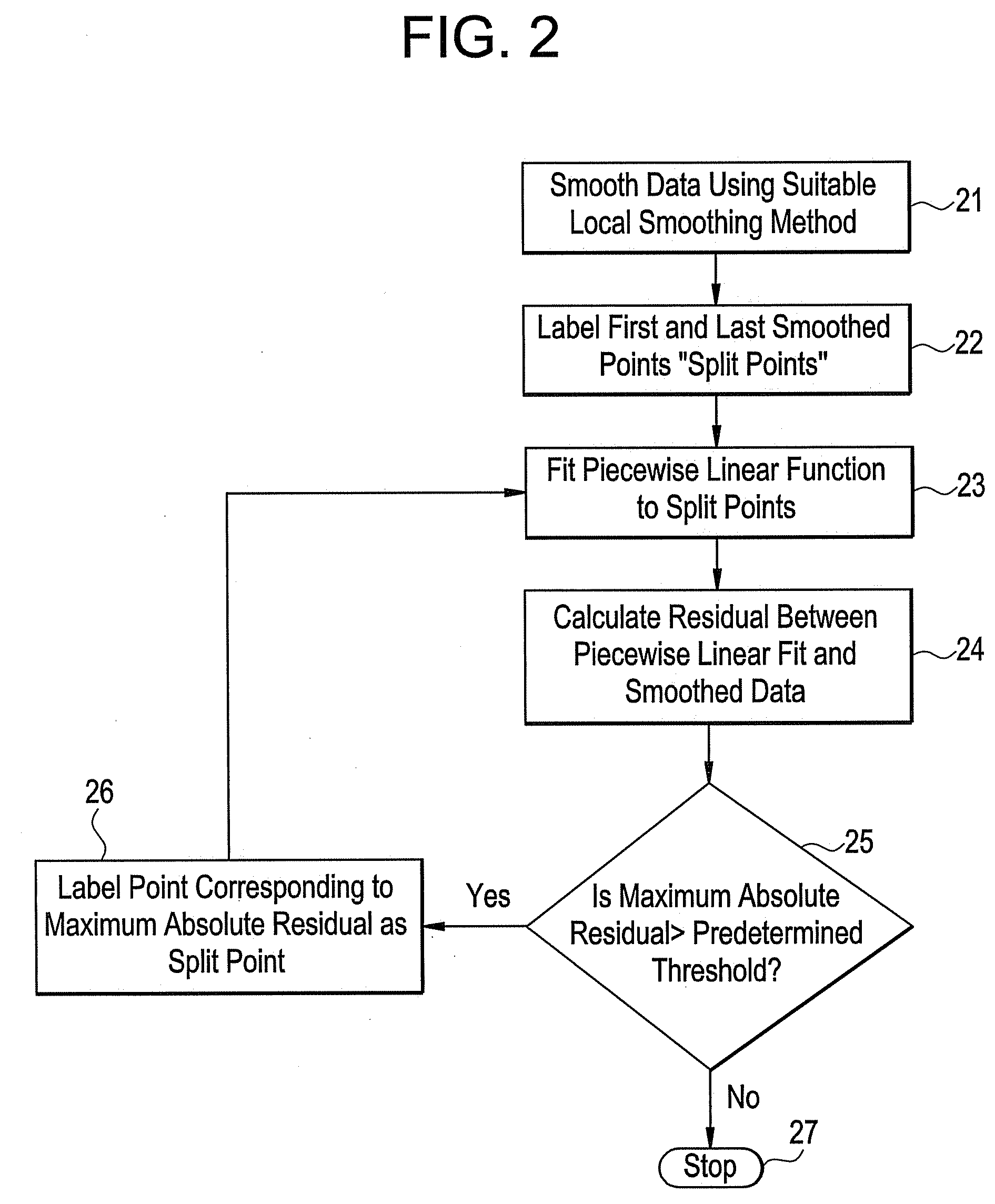
A method for fault detection and localization calls for obtaining a data set, smoothing the data set, identifying a plurality of split points within the data set, fitting a piecewise linear function to the plurality of split points; and determining a residual between the function and the smoothed data set. Related systems and computer program products are disclosed and claimed.

Description

BACKGROUND OF THE INVENTION[0001]1. Field of the Invention[0002]The teachings herein relate to system prognosis in general, and fault detection and localization in particular.[0003]2. Description of the Related Art[0004]Abnormal condition detection is an important first step in system prognosis. Abnormal conditions, also known as faults, are the first sign of a potential equipment failure at some future time. Detecting abnormal conditions implies, at the very least, detecting change in time series data from one or more sensors. Having detected that there has been a change, one often further desires to precisely locate the time of the change, (e.g., to allow in a manufacturing system the removal of defective units).[0005]The direct cost of equipment failures is unavoidable: ultimately, the faulted component must be replaced. However, there are indirect costs to equipment failure that are in many cases far greater than the cost of the repair. One source of indirect costs is secondary ...

Claims


Application Information

Patent Timeline
IPC IPC(8): H04Q1/20
CPCG06F11/0751
Inventor EKLUND, NEIL HOLGER WHITE
Owner GENERAL ELECTRIC CO
Learn More