

Coaxial pumping apparatus with internal power fluid column
a technology of power fluid column and coaxial pump, which is applied in the field of pumps, can solve the problems of 85% maintenance costs account for approximately 10% of the total cost of operating a conventional pump, so as to reduce the number of moving parts, increase energy efficiency, and reduce maintenance costs
Active Publication Date: 2008-09-11
MCNICHOL RICHARD F
View PDF20 Cites 6 Cited by
- Summary
- Abstract
- Description
- Claims
- Application Information
AI Technical Summary
Benefits of technology
[0005]Numerous industries, and in particular the oil and gas industry, have long been interested in pumps having increased energy efficiency. Pump designs which reduce maintenance costs by reducing the number of moving parts and / or reducing the damage caused by suspended particles are also highly desirable. Piston type pumping apparatus having increased energy efficiency and / or reduced maintenance costs and methods of using same are provided.
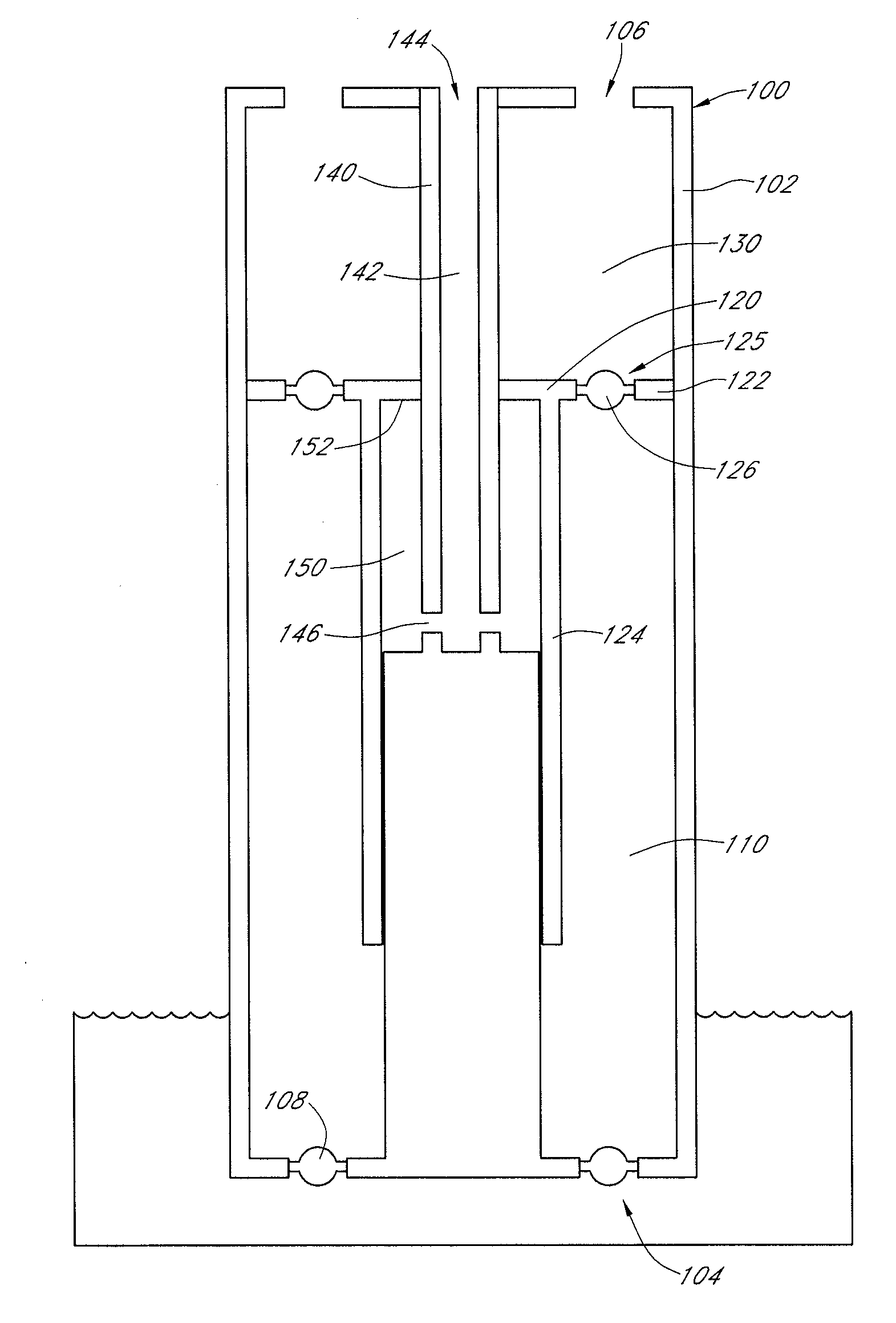
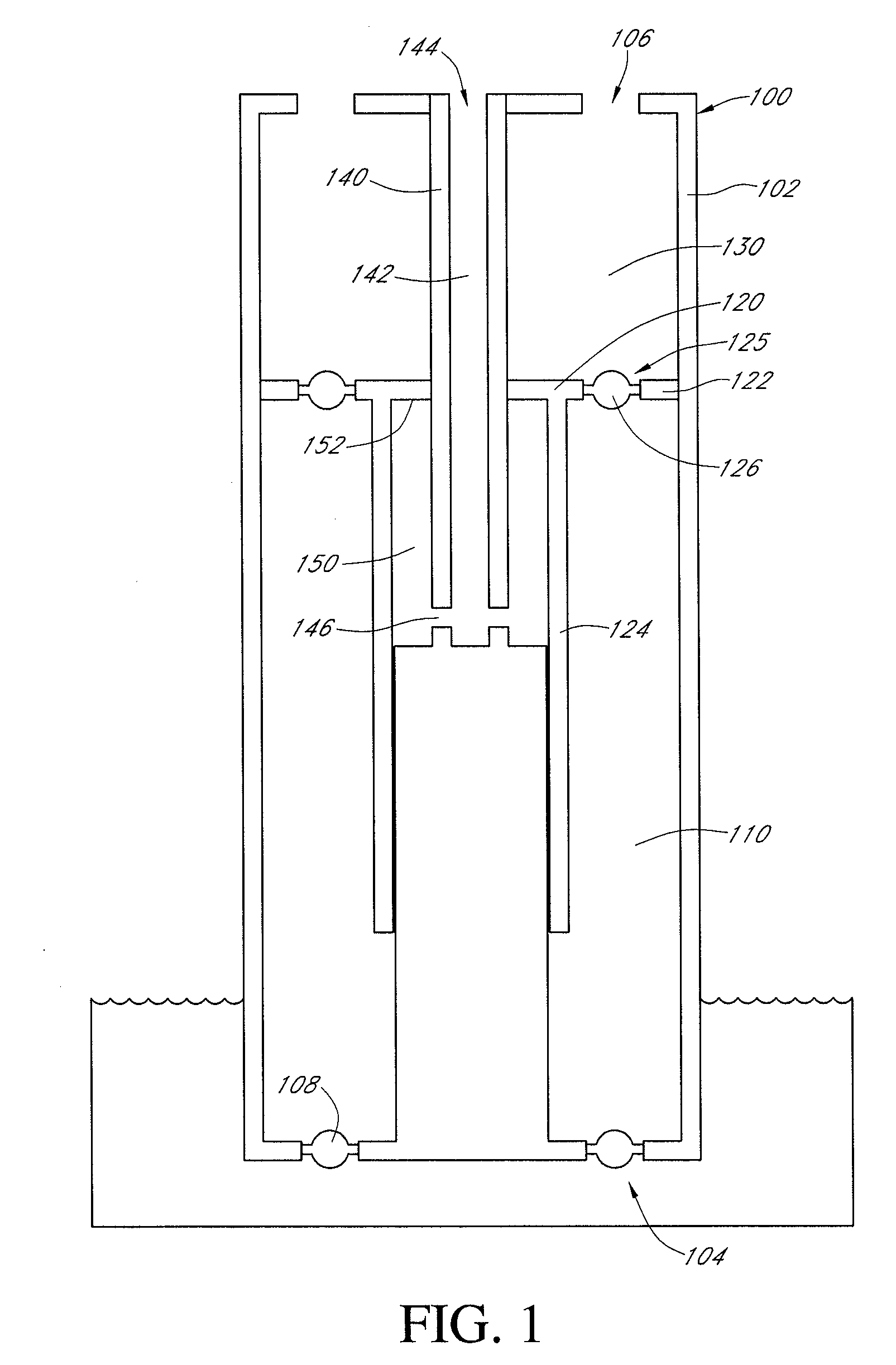
[0011]In certain embodiments, the oscillating pressure to the power fluid is provided by a column of power fluid extending to an elevation that is higher that the elevation at which the product fluid is being recovered. The pressure head created by this column of power fluid is sufficient to lift the transfer piston. A valve to the power fluid source can be closed and a release valve opened, at an elevation lower than the elevation at which the product fluid was recovered, in order to reduce the power fluid pressure and allow the transfer piston to lower.
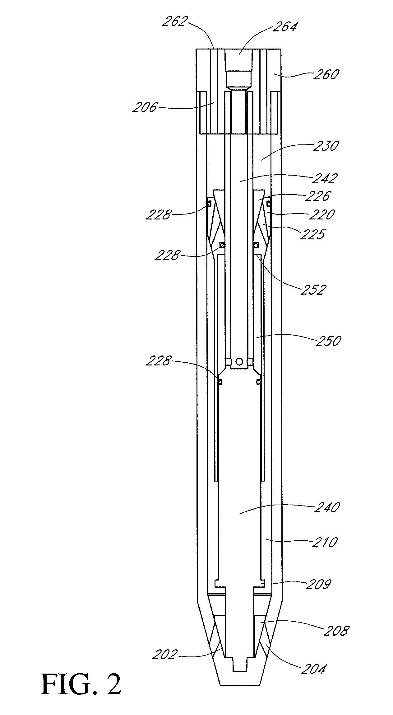
[0036]In a third aspect, a method is provided for pumping a fluid, the method comprising: introducing a power fluid into a power fluid chamber of a pumping apparatus via an internal power fluid column, whereby a transfer piston is lifted so as to close a transfer piston valve, whereby fluid to be pumped is drawn into a transfer chamber via an inlet valve; decreasing a pressure of the power fluid in the power fluid column and the power fluid chamber, whereby the transfer piston falls, the transfer piston valve is opened, and the inlet valve is closed, whereby the fluid to be pumped passes from the transfer chamber via the transfer piston valve into a product chamber; and increasing the pressure of the power fluid in the power fluid column and the power fluid chamber, whereby the transfer piston is raised, the transfer piston valve closes, and the transfer piston valve closes, such that fluid to be pumped in the product chamber is forced out of the product chamber, such that the fluid is pumped.
Problems solved by technology
It has been estimated that approximately 85% of the total cost of operating a conventional pump is attributable to energy consumption.
Similarly, maintenance costs account for approximately 10% of the total cost of operating a conventional pump.
Method used
View moreImage
Smart ImageViewing Examples

Examples
example 1
[0270]for a=0.1; and r=0.8
Eff=100r(1+a)(1-a)+(a-(1-r))(1+a),=801.10.9+(0.1-0.2)1.1,=801.22-0.11.1,=801.22-0.091,Eff=70.9%
example 2
[0271]for a=0.1; and r=0.5
Eff=100r(1+a)(1-a)+(a-(1-r))(1+a)=501.10.9+(0.1-0.5)1.1=501.22-0.41.1=501.22-0.364Eff=58.4%
example 3
[0272]for a=0.01; and r=0.8
Eff=100r(1+a)(1-a)+(a-(1-r))(1+a)=801.010.99+(0.01-0.2)1.01=801.22-0.191.01=801.22-0.188Eff=71.4%
Login to View More PUM
 Abstract
A pump having an increased energy efficiency is provided. The pump has an internal power fluid column and a transfer piston which is reciprocatingly mounted about the power fluid column. The transfer piston defines a product fluid chamber, located above the transfer piston valve, and a transfer chamber, located below the transfer piston valve. The power fluid column has at least one passageway, which allows the fluid inside the power fluid column to be in communication with a power fluid chamber. The power fluid chamber, the transfer chamber, and the product chamber are situated coaxially about the power fluid column.
Description
CROSS-REFERENCE TO RELATED APPLICATIONS[0001]This application claims the benefit under 35 U.S.C. § 119(e) of U.S. provisional application Ser. No. 60 / 898,377, filed Jan. 30, 2007, the disclosure of which is hereby expressly incorporated by reference in its entirety and is hereby expressly made a portion of this application.FIELD OF THE INVENTION[0002]The present application relates generally to pumps, and more particularly to piston type pumps having increased energy efficiency, systems incorporating such piston type pumps, and methods of operating piston type pumps.BACKGROUND OF THE INVENTION[0003]It has been estimated that approximately 85% of the total cost of operating a conventional pump is attributable to energy consumption. Moreover, pumping systems account for nearly 20% of the world's electrical energy demand and range from 25% to 50% of the energy required by industrial plant operations.[0004]Similarly, maintenance costs account for approximately 10% of the total cost of o...
Claims
Login to View More Application Information
Patent Timeline
 IPC IPC(8): F04B53/12
CPCF04B47/08F04B9/1056F04B19/22F04B53/12F04B53/14F04B53/16
Inventor FISHER, NORMMCNICHOL, RICHARD FREDERICK
Owner MCNICHOL RICHARD F