Sternum Reinforcing Device to be Used After a Sternotomy or a Sternal Fracture

a technology of sternotomy and sternal fracture, which is applied in the field of sternum reinforcing device to be used after sternotomy or sternal fracture, can solve the problems of wire breaking, infection and mediastinitis risk, and the current method of medial sternotomy is not free of complications, and achieves the effect of high risk of damag

Active Publication Date: 2008-09-11
SIC BREVETTI SRL
View PDF31 Cites 156 Cited by
  • Summary
  • Abstract
  • Description
  • Claims
  • Application Information

AI Technical Summary

Benefits of technology

[0010]Yet a further object of the invention is to allow the sternal halves be closed during an operation for sternal dehiscence particularly without being necessary to separate any adherence being formed in meanwhile, which would involve a high risk of damage to the heart and any bypasses and relevant ducts.
[0011]Yet another object ...

Problems solved by technology

However, both the medial sternotomy and the current methods are not free of complications.
The complications of the sternal wound, usually due to the sternum instability, range from prolonged thoracic pains, which cause inconveniences and related respiratory disorders up to the deh...

Method used


Image

  • Sternum Reinforcing Device to be Used After a Sternotomy or a Sternal Fracture
  • Sternum Reinforcing Device to be Used After a Sternotomy or a Sternal Fracture
  • Sternum Reinforcing Device to be Used After a Sternotomy or a Sternal Fracture

Examples


first embodiment

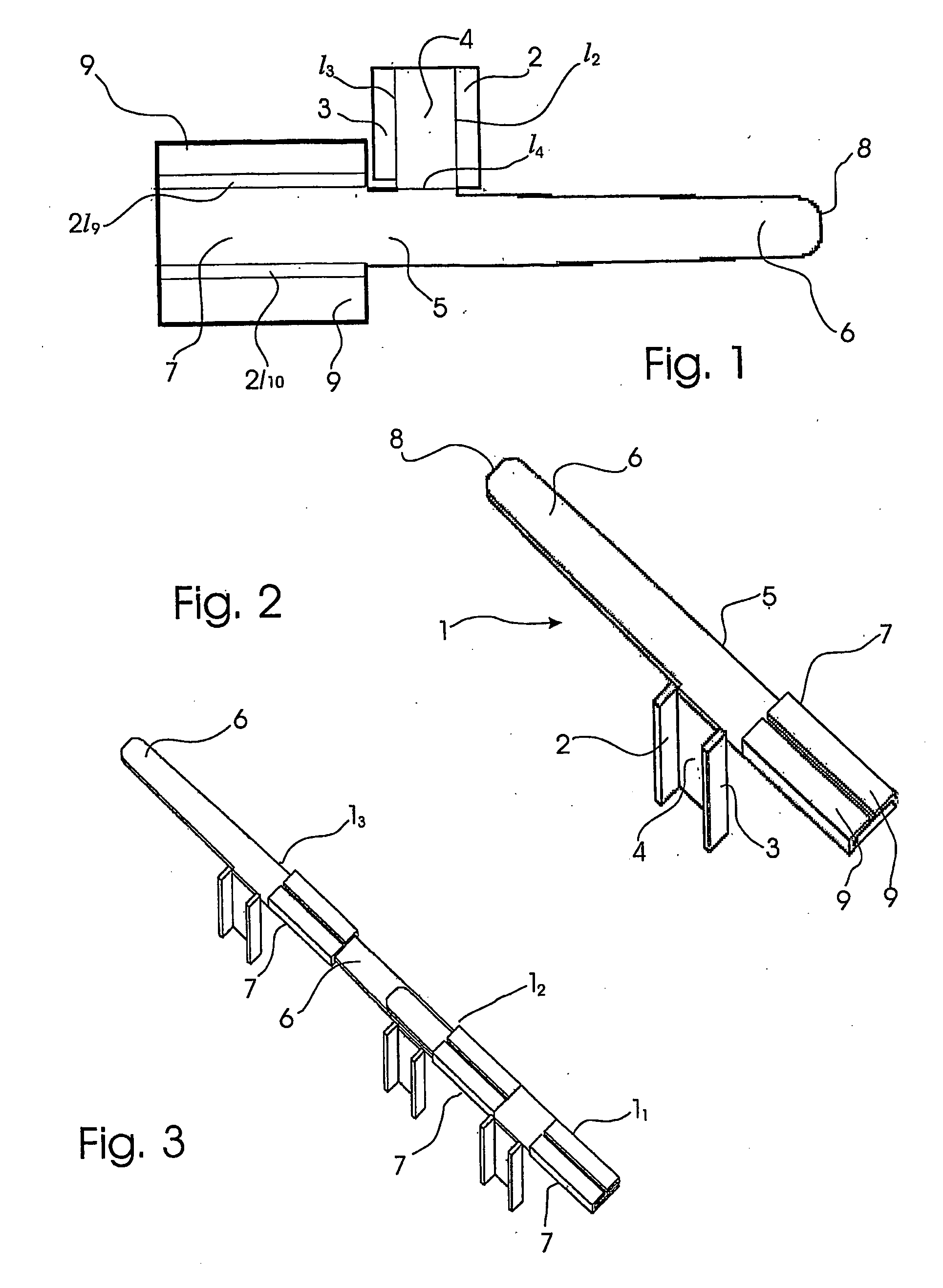
[0025]With reference to the drawings, shown in the plan view of FIG. 1 is the device according to the present invention in a semifinished condition, i.e. in the form of a punched plate blank (totally lying in the plane of the drawing sheet). The reinforcing device can be manufactured from a sheet of biocompatible material, e.g. stainless steel, being shaped by punching or other cutting process such as electrical discharge machining or laser cutting, etc. into a modular elongated member. Mechanical and technological characteristics of the material are selected in order to assure suitable mechanical working properties, usefulness and functionality to the device. Obviously, the reinforcing device can be obtained by machining as well as by casting, or from a not metallic material and by a different working method.

[0026]The elongated modular member 1 is shaped in a such way that a small body portion 4 is made in the form of a gusset in a intermediate position of the elongated modular mem...

second embodiment

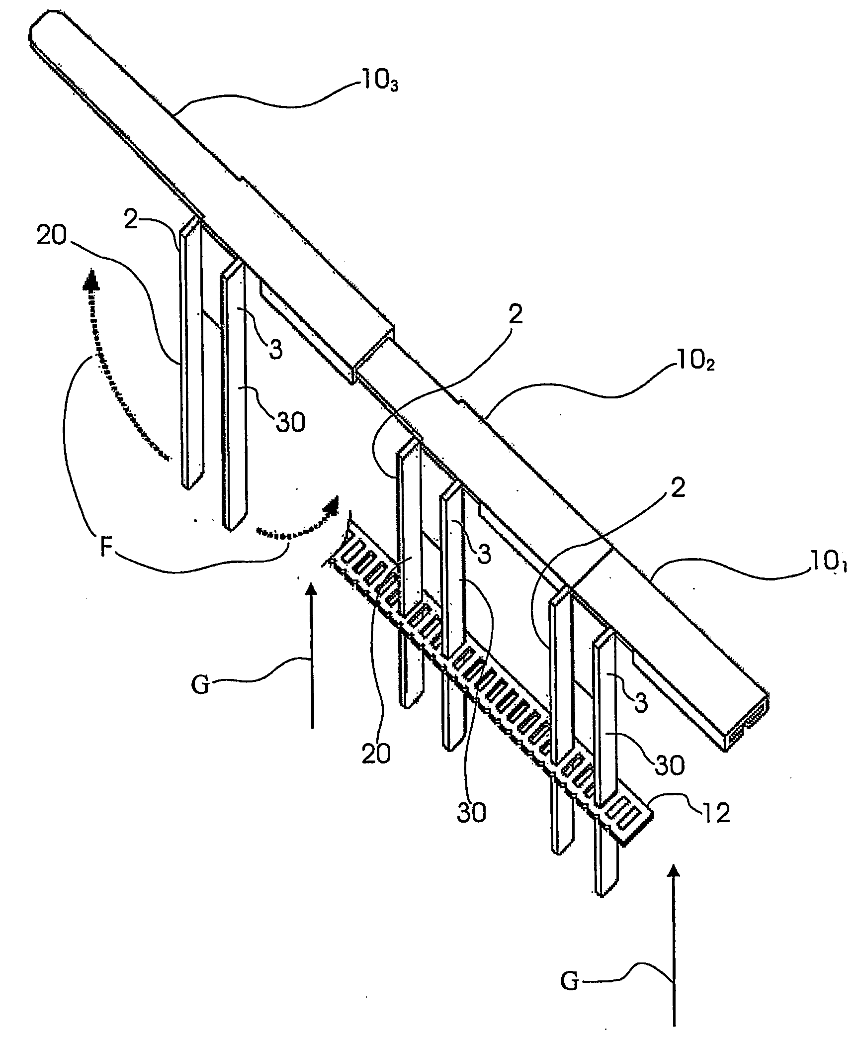
[0033]With reference to FIG. 4, therein the modular device according to the present invention, indicated as 10 as a whole, is shown by a plan view similar to that in FIG. 1.

[0034]For clarity sake, in describing the second embodiment similar reference numerals and signs are used to indicate parts that are identical or similar to those of the first embodiment. The second embodiment differs from the first embodiment as the edges 2, 3 extend from the body portion 4 to form legs 20, 30.

[0035]The punched plate blank in FIG. 4 is shown in its erected form, ready for its use, in the perspective view of FIG. 5. Therein the body portion 4 is shown bent orthogonally downwards, thus as if it penetrates the drawing sheet, and the two lateral legs 20 and 30 are bent substantially 90 degrees outwards. As for the first embodiment, the fins 9, 9 are bent to form a channel-shaped cross-section. The counter-rotating arrows F indicate that the lateral legs 20, 30 can be bent in the opposite direction t...


PUM


Abstract

A sternum reinforcing device to be used after a sternotomy or a sternal fracture, made of a biocompatible material, comprises an elongated modular member (10) with a pair of legs (20, 30), that are joined each other by a body portion (4), and a pair of arms (6, 7). The legs (20, 30) can be fitted in an intercostal space of the thorax of a patient, laterally to the sternum, and can be bent in a mutually opposite direction, on the internal side of the thorax, after being fitted therein. The arms (6, 7), extending from one side to the other of the body portion (4) and orthogonally to the pair of legs (20, 30), constitute a male part and a female part, respectively, of a prismatic type coupling for consecutive modular members.

Description

TECHNICAL FIELD[0001]This invention relates to a sternum reinforcing device to be used after a sternotomy or a sternal fracture.BACKGROUND ART[0002]The median sternotomy is a very usual operation in the field of heart surgery. The sternum or its portion of a patient is sawn by a saw or other cutting means. When all the sternum is severed in two, its sternal halves are spread apart laterally the one from the other so that mediastinum structures can be exposed. As a result, a large aperture is formed in the thoracic cavity, which permits an optimal surgical access to the heart and great vessels and also is well tolerated by the patient.[0003]Once the operation is completed, the two sternal halves are rejoined. Traditionally, several means, such as Mersilene fibres, steel wires, metal and plastic bands, nitinol clamps, etc. are used for a sternal closure in order to assure the sternal stability and the recovery of the patient. The most usual current method of doing this is to use steel...

Claims


Application Information

Patent Timeline
IPC IPC(8): A61B17/56A61B17/80A61B17/08A61B17/82
CPCA61B2017/081A61B17/823A61B17/8076A61B17/56A61B17/58A61F2/28
Inventor ZEITANI, JACOB
Owner SIC BREVETTI SRL
Why Eureka
Try Eureka