Slope compensator for pedestal for elevated floors

a technology for pedestals and floors, applied in the direction of building scaffolds, machine supports, other domestic objects, etc., can solve the problems of not always immediately apparent, awkward use of existing pedestals incorporating slope adjustment, etc., and achieve the effect of increasing the stability of the pedestal and reducing or preventing the relative movement of the bas

Inactive Publication Date: 2008-09-18
LEE IN OK
View PDF10 Cites 85 Cited by
  • Summary
  • Abstract
  • Description
  • Claims
  • Application Information

AI Technical Summary

Benefits of technology

[0029]the base defines an open top and is internally threaded to receive a lower part of the spacer element, which is externally threaded to engage with the internally threaded portion of the base such that relative rotation of the two adjust the height of the pedestal and characterised by a locking ring which is located on the externa...

Problems solved by technology

Problems arise when forming a raised surface on a sub floor/subsurface which is not itself horizontal such as roof terrace which will typically slope at an angle of up to 5% in order to allow water run off.
Although height adjustable pedestals with means for compensating for slope, are known to address the problem of slope, existing pedestals incorporating slope adjustment tend to be rather awkward to use and adjust.
One common proble...

Method used


Image

  • Slope compensator for pedestal for elevated floors
  • Slope compensator for pedestal for elevated floors
  • Slope compensator for pedestal for elevated floors

Examples


Embodiment Construction

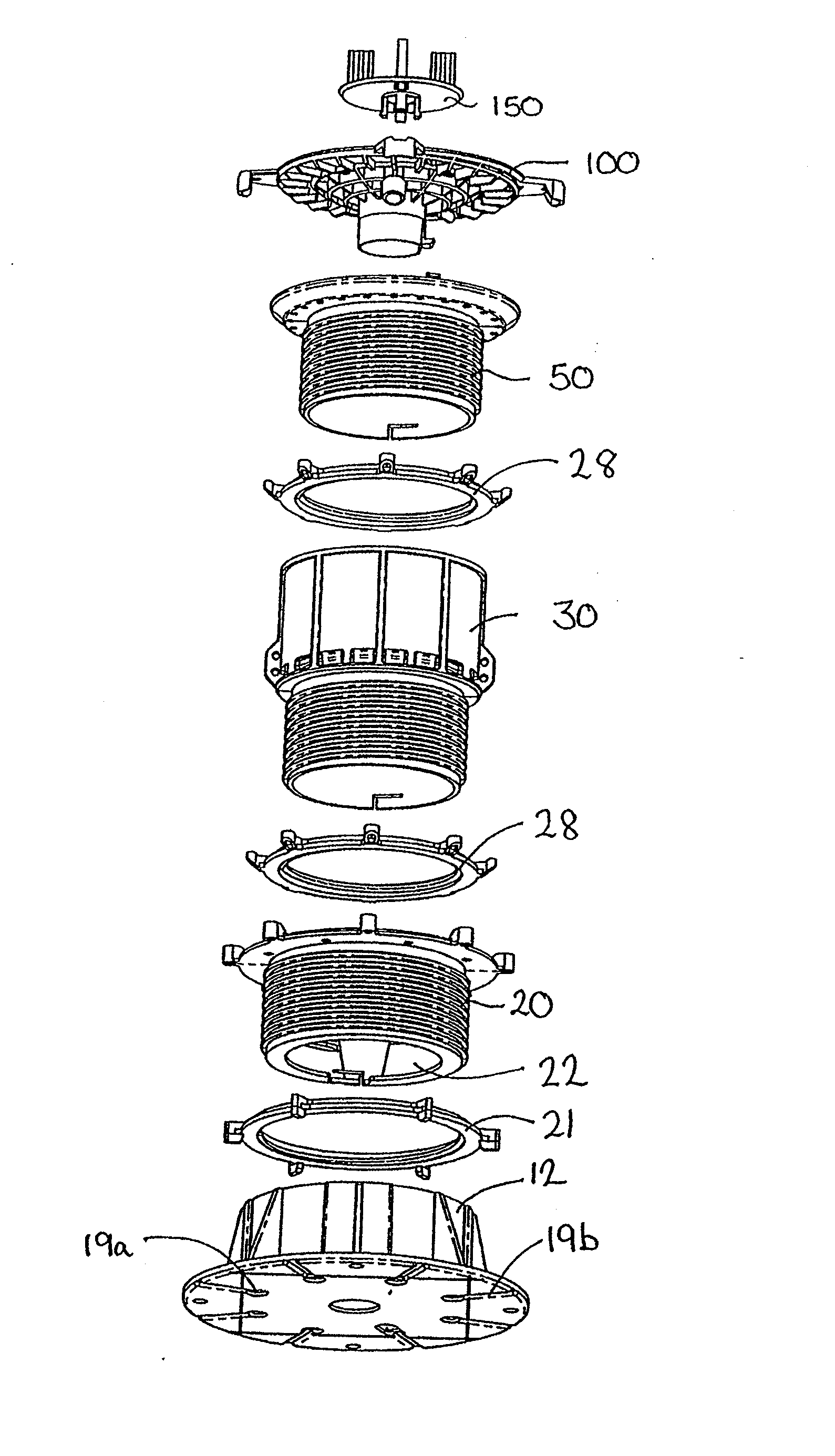
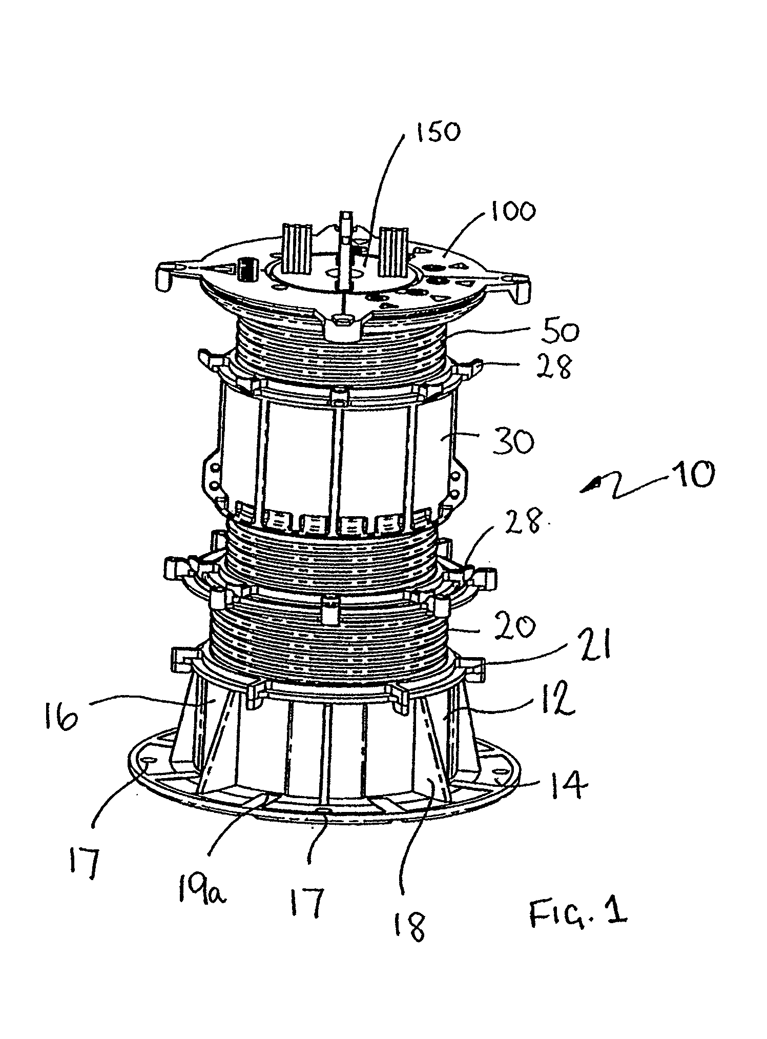
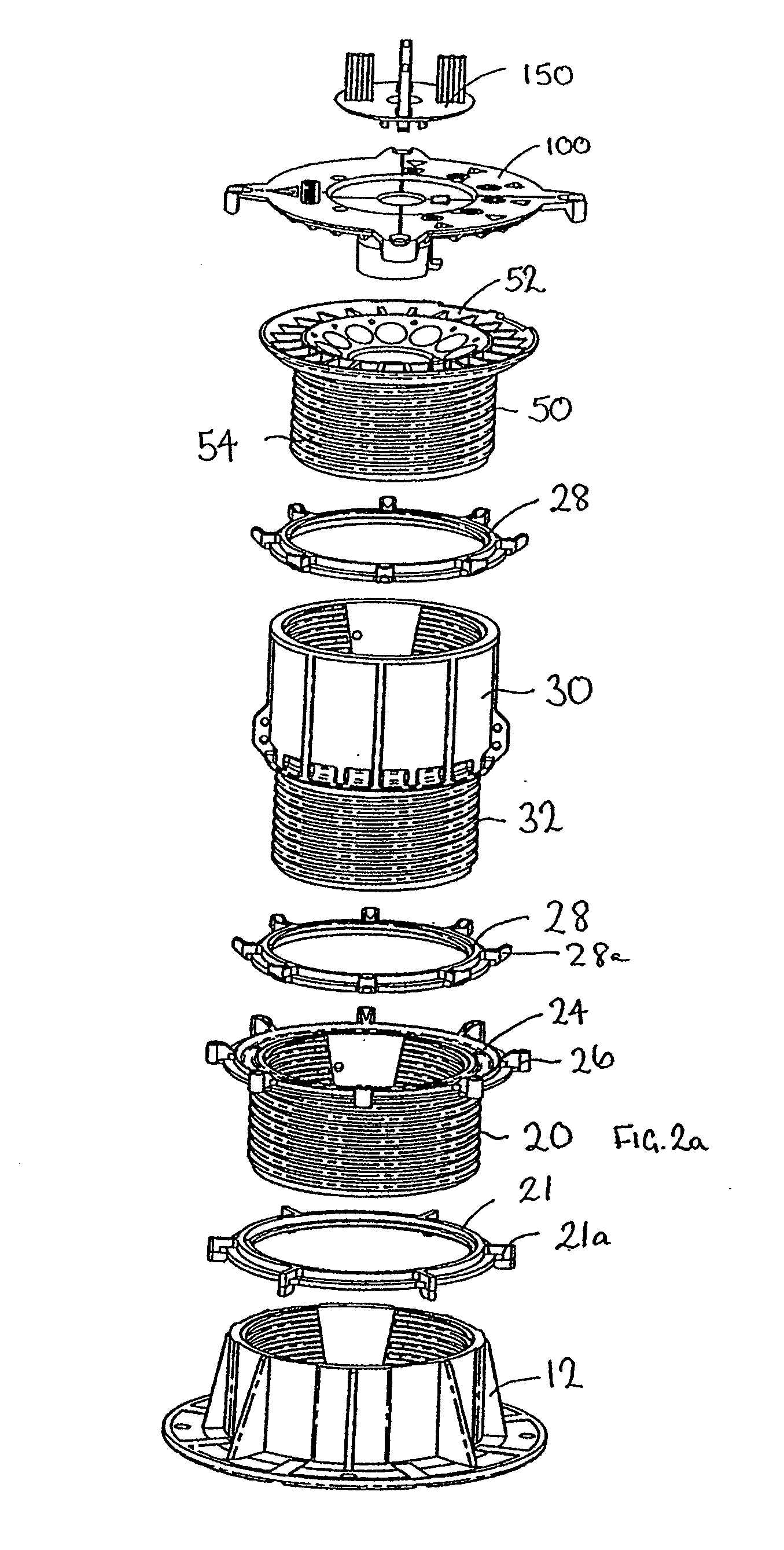
[0055]Referring to the drawings, FIG. 1 shows a height adjustable pedestal 10 incorporating slope adjustment, embodying the present invention comprising a number of components which can also be seen in the exploded views 2a and 2b. The height adjustable pedestal comprises a base element 12 comprising a circular planar base plate 14 defining a plane on which the pedestal stand in use, and an annular cylindrical portion 16 extending upwards from the base. The base is rimless to minimise collection of water. A series of holes 17 are defined in the base for bolting, or otherwise fixing, the base to a substrate. The cylindrical portion 16 is internally threaded. A series of generally triangular buttresses / webs 18 extend from the base plate 14 to the outer face of the cylindrical portion 16. Drainage holes 19a are also provided for drainage between the vertical webs to prevent build up of water, particularly when the base is inclined. FIG. 2b also shows drainage channels 19b which extend ...


PUM


Abstract

A slope adjustable head for an adjustable pedestal (10) for supporting beams, panel members, typically pavers, in accurate edge aligned relation, in a level plane is disclosed. The pedestal (10) includes a base block (12) and a series of inter-engaging threaded annular elements (20, 30) which can be rotated relative to each other to adjust the height of the top of the pedestal in a screw jack fashion. A slope compensator is located at the top of the pedestal and comprises a slope compensation plate (100) and a head member (50). The head member (50) defines a concave surface having a defined radius of curvature. The slope compensation plate (100) defines a corresponding convex surface having the same radius of curvature and sits on top of the head member. The pedestal (10) is calibrated to allow adjustment for typically zero to five percent in one percent increments. The top member defines a central aperture (56) and a series of holes (72) arranged in a spiral around the central aperture. The adjustment member defines a depending central cylindrical portion (110) which locates in the central aperture (56) and two diametrically opposed depending pegs (132, 134) spaced either side of the central cylindrical portion which locate in the holes of the top member. Rotation of the slope compensation plate (100) about its centre of curvature causes the angle of the adjustment plate relative to the vertical axis to change thus allowing for compensation for the slope of the surface on which the pedestal is standing.

Description

CROSS-REFERENCE TO RELATED APPLICATIONS[0001]The present application is a continuation-in-part of PCT / AU2006 / 001613 which claims priority from Australian Provisional Patent Application No 2005905990 filed on 28 Oct. 2005, the contents of both applications being incorporated herein by reference.FIELD OF THE INVENTION[0002]This invention relates to a slope compensator for a pedestal for elevated floors.BACKGROUND OF THE INVENTION[0003]It is known to provide elevated or raised floors, also known as pedestal floors. Elevated flooring incorporates a number of height adjustable pedestals which are uniformly distributed over a subsurface / sub floor such as a concrete floor of a multi-story building, a roof, terrace, or any other surface on top of which it is desired to locate an elevated floor. Other non-exhaustive applications of pedestal floors include technical floors for laboratories, fitting out old buildings, patios, balconies, swimming pool surrounds and decking. The pedestals cooper...

Claims


Application Information

Patent Timeline
IPC IPC(8): E04G1/22E04B5/02
CPCE04F15/02482E04F15/02476E04F15/02488E04F15/024E04F15/00E04G27/00E04B5/00
Inventor LEEGREAVES, HENRY
Owner LEE IN OK
Why Eureka
Try Eureka