Pipette and sealing mechanism for plunger

Inactive Publication Date: 2008-09-18
NICHIRYO CO LTD
View PDF3 Cites 23 Cited by
  • Summary
  • Abstract
  • Description
  • Claims
  • Application Information

AI Technical Summary

Benefits of technology

[0019](4) Still another object of the present invention is to provide a pipette in which the tubular body (1) is formed from a finely foamed molded material such as polyphenyl sulfone. This makes the body (1) resistant to a conduction of the heat of a hand therethrough when grasped by the hand so that fluctuations in the suction volume that may result from the influence of the hand heat are very small.
[0020](5) A still further object of the present invention is to provide a pipette in which a first engagement portion provided on either an upper ejector pipe (41) or a lower ejector pipe (42) is engageable in a switchable manner with any one of a plurality of second engagement portions provided on the other so that the lower end position of the lower ejector pipe (42) may be varied. Accordingly, if tips (46) of various standardized sizes are attached on the outer periphery of the nozzle tip (24), the lower end position of the lower ejector pipe (42) can be adjusted in accordance therewith, thereby enabling a smooth ejecting operation and widening the applicability of the pipette.
[0021](6) Still another object of the present invention is to provide a pipette in which a volume variably setting and calibration pipe (4) is forcibly moved in an axial direction to disengage a clutch claw (4b) of the calibration pipe (4) from a meshing gear portion (3a) of the clutch pipe (3), and then rotating the calibration pipe (4) to drive a counter mechanism (51) without varying the actual suction volume to thereby vary only an indication of a numerical value of the suction volume to perform the calibration. This allows the calibration to be performed easily without the need for a special-purpose jig or the like for the calibration.
[0022](7) Still another object of the present invention is to provide a plunger sealing mechanism for a pipette which has an improved sealing performance. An O-ring (103) is pressed against an inclined inner surface (121a) of a tubular cylinder (121) by an O-ring pressing spring (104) with a predetermined force so that a component of the predetermined force that is in a direc

Problems solved by technology

Thus, the load of the first-stage spring (10) once set at the initial stage remains constant during the above movement, so that the drawback as in th

Method used


Image

  • Pipette and sealing mechanism for plunger
  • Pipette and sealing mechanism for plunger
  • Pipette and sealing mechanism for plunger

Examples


first embodiment

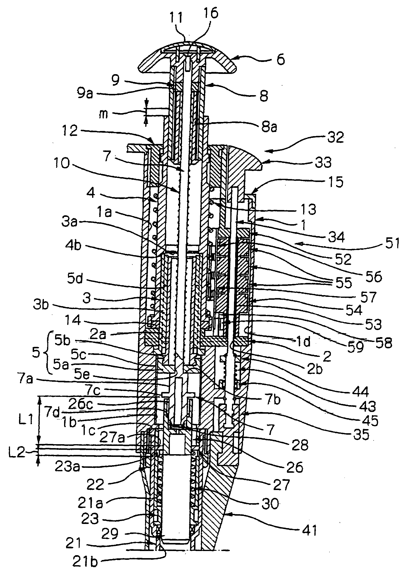
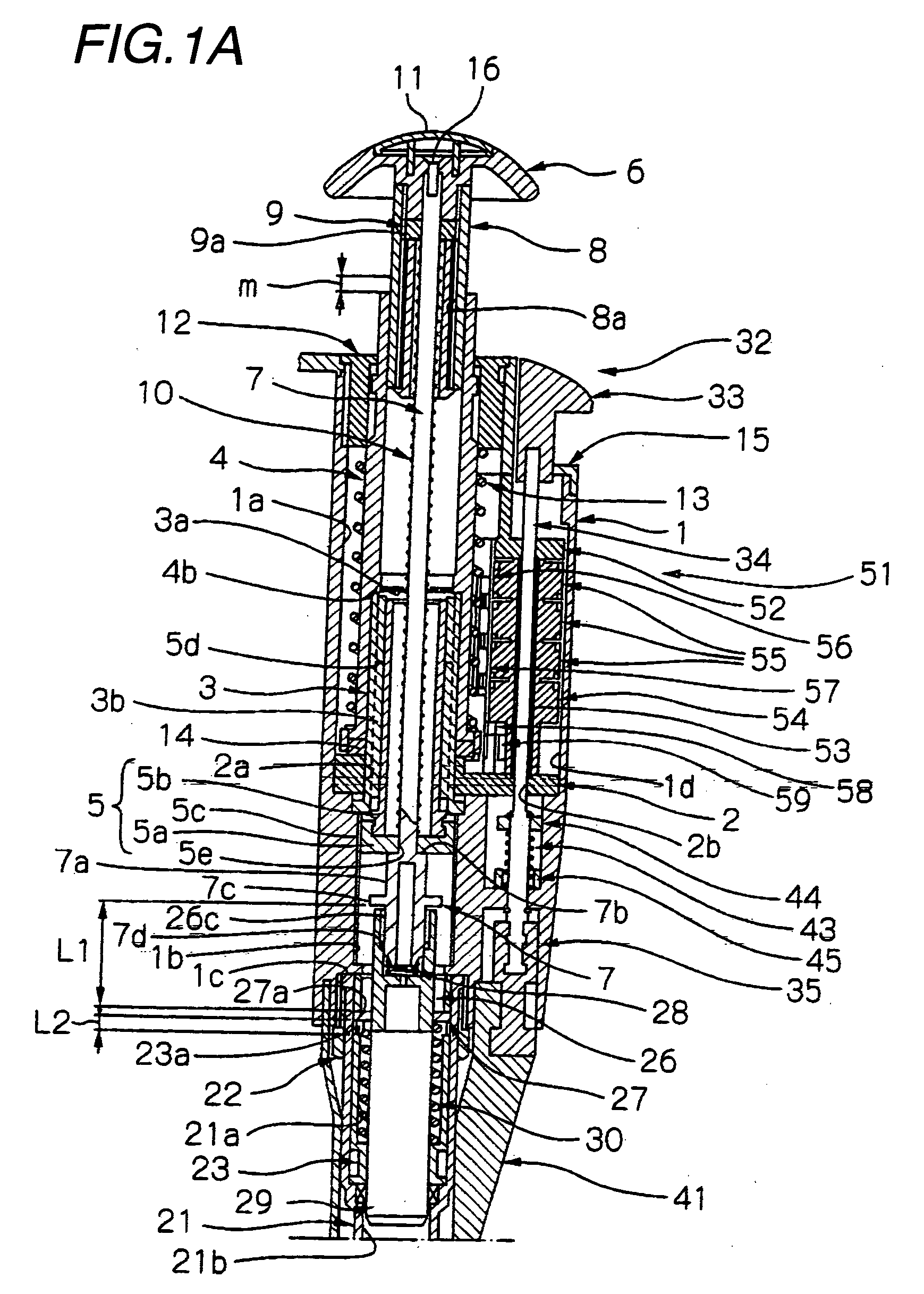
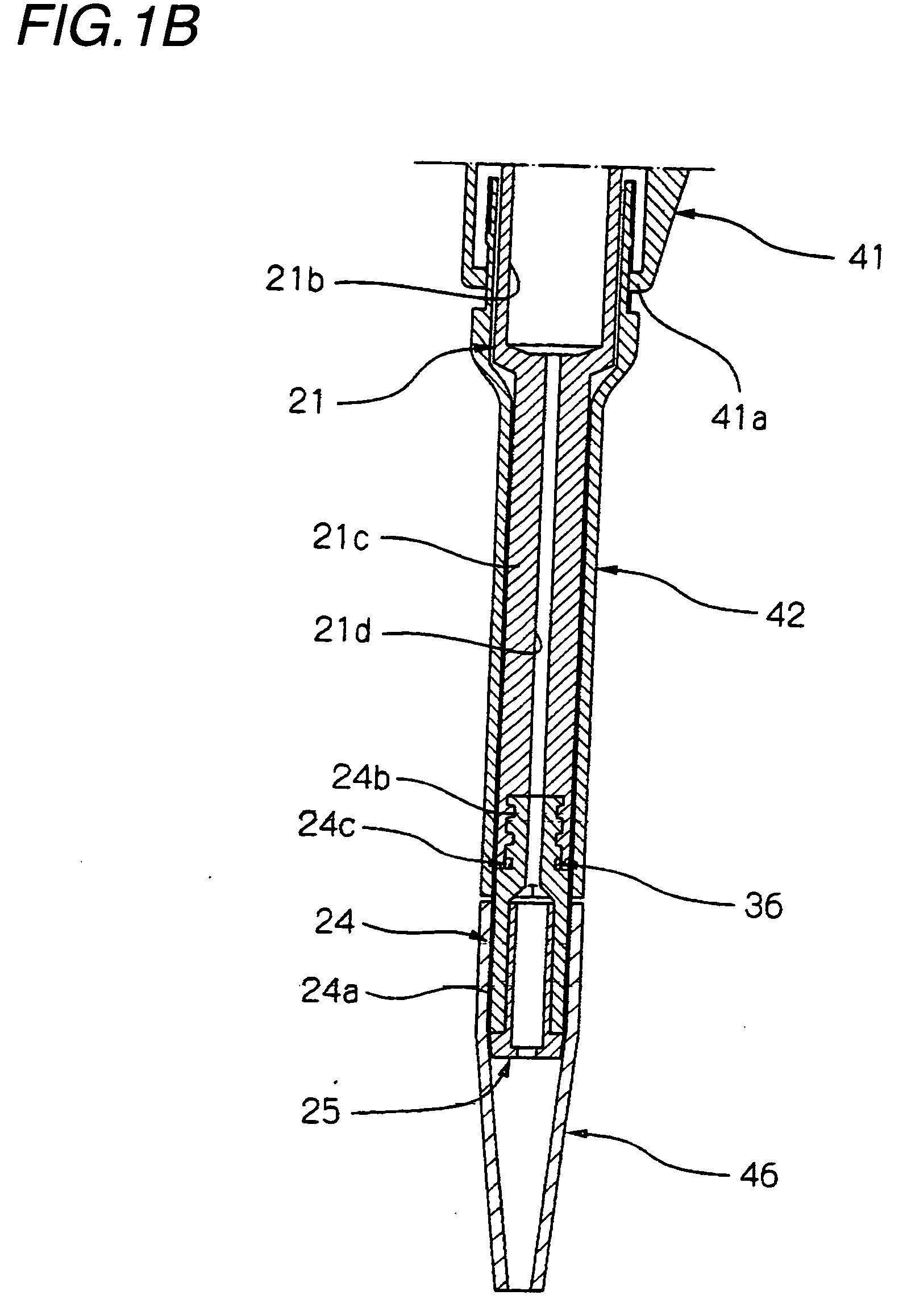
[0091]FIG. 1A is an enlarged longitudinal sectional view of an upper half of a pipette according to the present invention. FIG. 1B is an enlarged longitudinal sectional view of a lower half of the same. FIGS. 2 and 3 are longitudinal sectional views of the pipette in states upon completion of a first-stage pushing down and of a second-stage pushing down, respectively. Please note that, regarding FIG. 4 and thereafter, the left side in the figures basically corresponds to the upper side in FIGS. 1 to 3, and the right side in the figures corresponds to the lower side in FIGS. 1 to 3.

[0092]In FIGS. 1 and 4, 1 denotes a tubular body of a variable pipette according to the present invention, which has threaded holes 1b and 1c coaxially provided with a central hole 1a, and an ejector shaft hole 1d. Since this tubular body 1 is formed from a finely foamed molded material such as, for example, polyphenyl sulfone, the heat of a hand, when the body 1 is grasped by the hand, is difficult to be ...

second embodiment

[0124]a pipette according to the present invention will now be described with reference to FIGS. 24 to 32. In these figures, the same parts as in FIGS. 1 to 23 are given the same reference characters, and their description will be omitted. This second embodiment in particular has a feature in a plunger sealing mechanism provided between the plunger 29 and a tubular cylinder 121 inside which the plunger 29 is slidably fitted.

[0125]The plunger sealing mechanism, as shown in FIGS. 24 and 25, is made up of an O-ring retention ring 101 fitted around the plunger 29, a seal ring 102 fitted around the plunger 29, an O-ring 103 interposed between the O-ring retention ring 101 and the seal ring 102, and an O-ring pressing spring 104 which axially presses the O-ring retention ring 101 with a predetermined force to press the O-ring 103 against an inclined inner surface 121a of the tubular cylinder member 121 so that the seal ring 102 is radially inwardly pressed against the outer periphery of t...


PUM


Abstract

A pipette includes a tubular body (1) having an internal circumferential threaded portion (1b); a stroke screw (5) provided inside the body (1) and having an external circumferential threaded portion (5c) for thread-engaging said internal circumferential threaded portion (1b); a volume variably setting member (4) disposed to be rotatable together with the stroke screw (5) as one unit and axially slidable relative thereto; a central shaft (7) provided inside said tubular body (1), which is coupled to a plunger (29) and operable to be pushed down; and a first-stage spring (10) interposed between an upper portion of said central shaft (7) and said stroke screw (5), which urges the central shaft (7) upward so that a predetermined portion (7b) thereof urgingly abuts against the stroke screw (5), wherein, by rotating said volume variably setting member (4) as appropriate, the stroke screw (5) is caused to rotate together therewith as one unit relative to the body (1) so that said stroke screw (5) and said central shaft (7) axially slide together as one unit apparently by a predetermined amount, thereby variably setting a suction volume of said pipette.
A plunger sealing mechanism includes an O-ring retention ring (101) fitted around said plunger (29); a seal ring (102) fitted around said plunger (29); an O-ring (103) interposed between said O-ring retention ring (101) and said seal ring (102); and an O-ring pressing spring (104) which axially presses said O-ring retention ring (101) with a predetermined force to press said O-ring (103) against an inclined inner surface (121a) of a tubular cylinder member (121) so that said seal ring (102) is radially inwardly pressed against an outer peripheral surface of said plunger (29) by a component of said predetermined force that is in a direction perpendicular to the axis of the pipette, wherein an inclination angle α of said inclined inner surface (121a) is 40° to 65° relative to the direction perpendicular to the axis of the pipette.

Description

TECHNICAL FIELD OF THE INVENTION[0001]The present invention relates to a pipette whose suction and discharge volume is variably settable and a sealing mechanism for a plunger used in the pipette.BACKGROUND OF THE INVENTION[0002]An example of a conventional variable pipette is composed of a resin-made substantially tubular body or pipette body (with a sampling chamber, i.e., cylinder chamber at its lower end), a metal sheath having an external circumferential thread which threadingly engages an internal circumferential thread of the pipette body, a central push rod of a hexagonal shape in cross section which is unrotatably and axially slidably inserted in a central hexagonal hole of the metal sheath, and a piston rod and a piston integral therewith which, at a position below the push rod, are urged upwardly into abutment against the lower end of the push rod by first and second coil springs (hereinafter referred to as a first-stage spring and a second-stage spring), all of which are ...

Claims


Application Information

Patent Timeline
IPC IPC(8): G01F25/00G01N1/14
CPCB01L3/0224B01L2200/14G01F11/027G01F11/023B01L2300/026
Inventor KOBAYASHI, MASASHISASAKI, JUN
Owner NICHIRYO CO LTD
Why Eureka
Try Eureka