
Minute structure inspection device, inspection method, and inspection program

a technology of inspection device and inspection program, which is applied in the direction of vibration measurement in solids, analysing solids using sonic/ultrasonic/infrasonic waves, instruments, etc., can solve the problems of difficult to perform highly accurate inspection, complicated and expensive testers are required, and the inspection is difficult to be precise. , to achieve the effect of accurate inspection, simple manner and accurate inspection

Inactive Publication Date: 2008-09-18
TOKYO ELECTRON LTD
View PDF11 Cites 11 Cited by
  • Summary
  • Abstract
  • Description
  • Claims
  • Application Information

AI Technical Summary

Benefits of technology

[0029]The minute structure inspection device, inspection method, and inspection program according to the present invention output the test sound wave to the minute structure upon testing, and evaluate the characteristic of the minute structure from the frequency response characteristic of the variable varying on the basis of the movement of the movable portion of the minute structure in response to the test sound wave, and therefore can accurately inspect the minute structure having the minute movable portion in a simple manner.

Problems solved by technology

As described in the above publication of unexamined patent application, even in the case where the device is varied (slightly in structure), fine adjustment should be performed to evaluate the characteristic of the acceleration sensor; however, highly accurate inspection is extremely difficult to perform under the condition that a flow rate of gas is controlled and the gas is uniformly blown toward the device, and even if the inspection is performed, a complicated and expensive tester has to be provided.
Further, in the case of the blowing of air, highly accurate inspection is difficult to perform with the air being made to have directivity, and blown toward a specific position.

Method used


Image

  • Minute structure inspection device, inspection method, and inspection program
  • Minute structure inspection device, inspection method, and inspection program
  • Minute structure inspection device, inspection method, and inspection program

Examples


embodiment 1

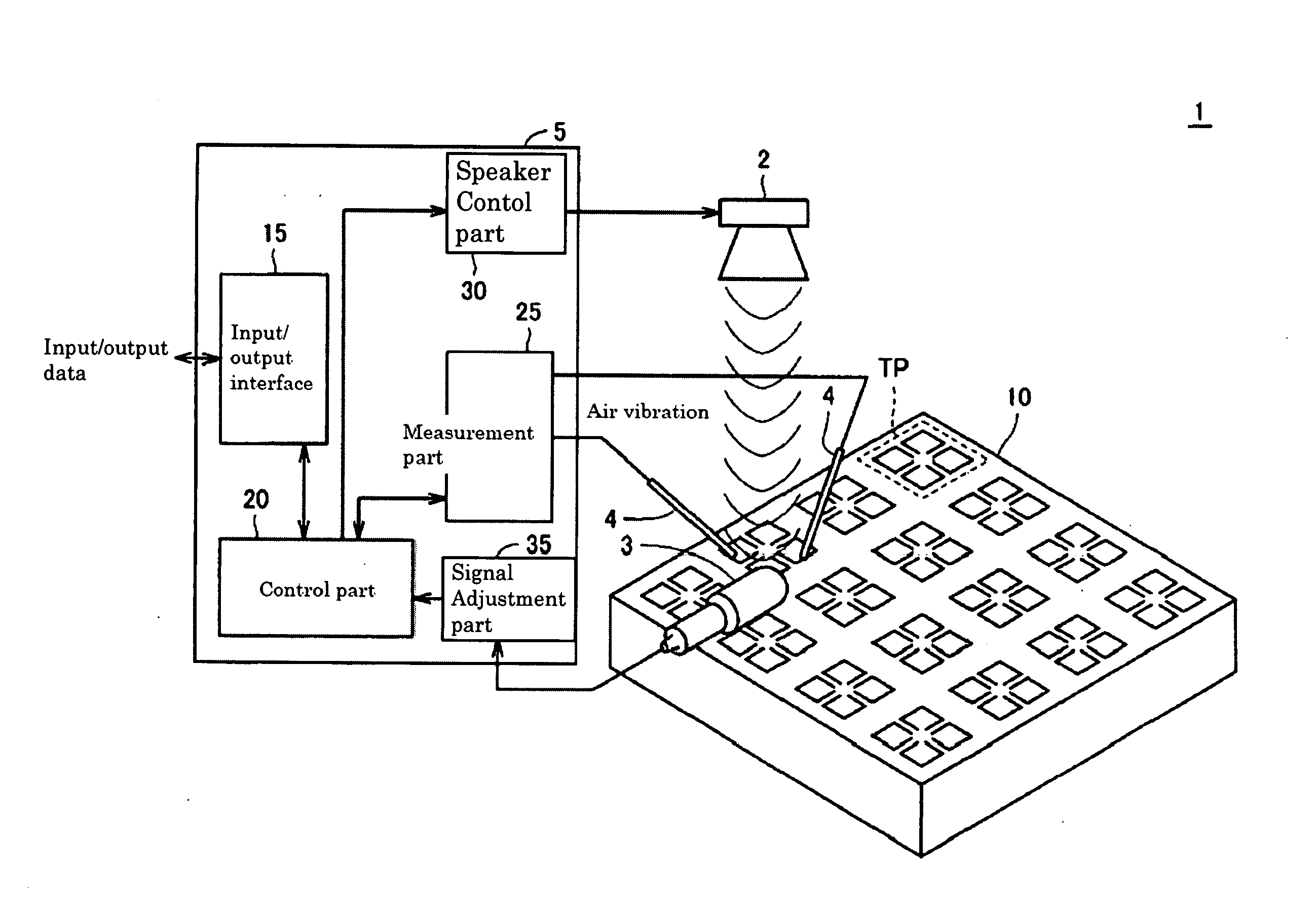
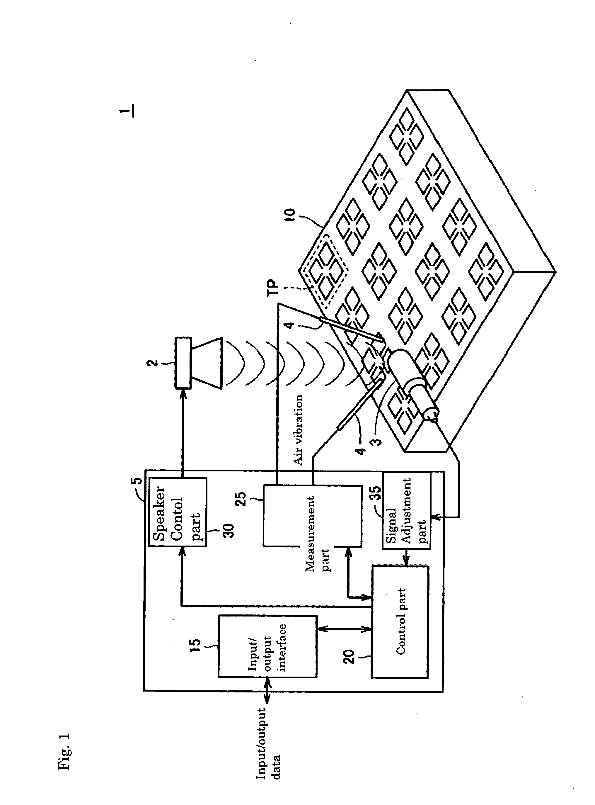
[0062]FIG. 1 is a schematic configuration diagram of a minute structure inspection system 1 according to Embodiment 1 of the present invention.

[0063]Referring to FIG. 1, the inspection system 1 according to Embodiment 1 of the present invention comprises a tester (inspection device) 5, and a substrate 10 formed thereon with a plurality of minute structure chips TP each having a minute movable portion.

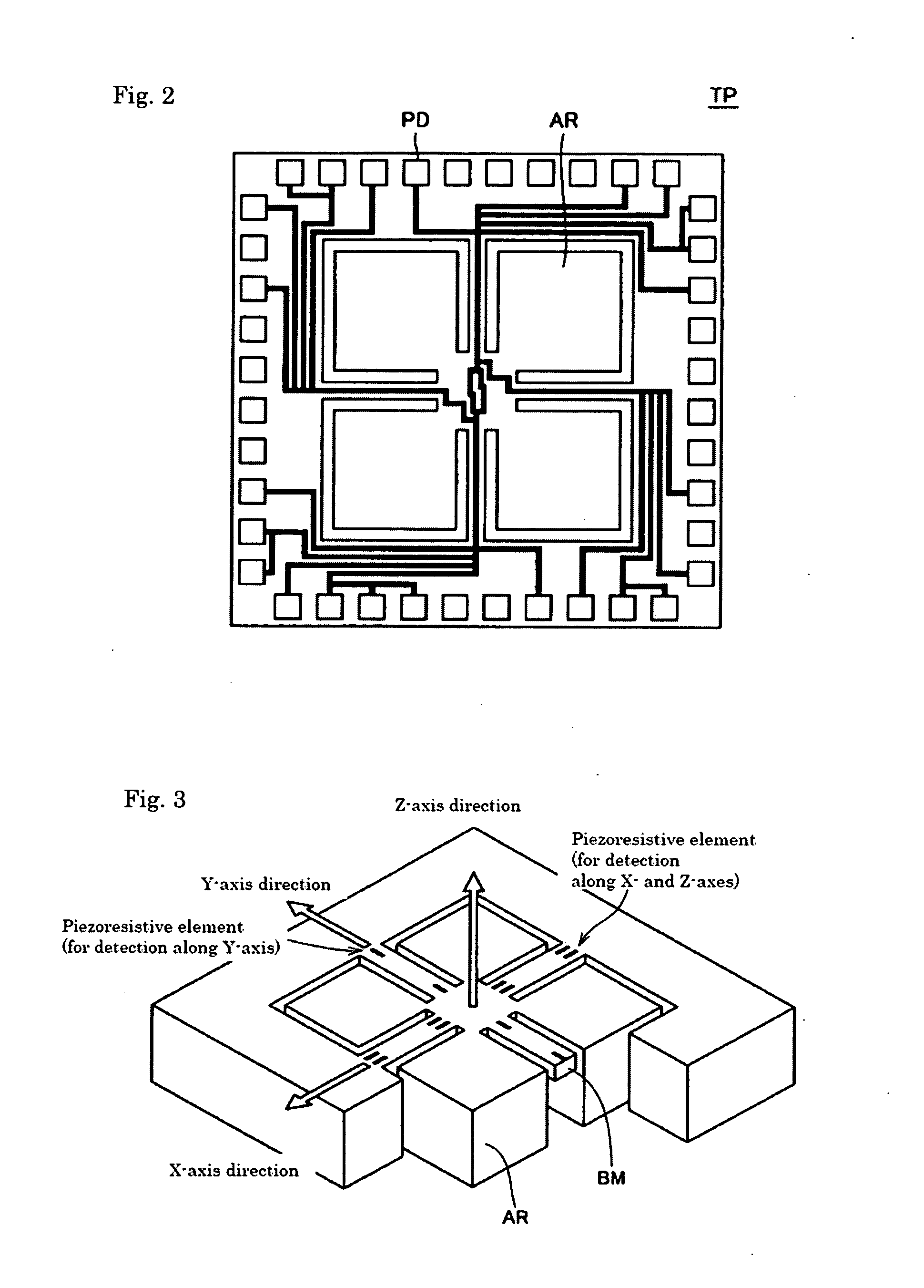
[0064]In this embodiment, a triaxial acceleration sensor, which is one of multiaxial sensors, is described as an example of a minute structure to be tested. The tester 5 comprises: a speaker 2 for outputting a sound wave, which is a compressional wave; input / output interface 15 for communicating input / output data between the outside and inside of the tester; control part 20 for controlling the entire tester 5; probes 4 used for contact with a test object; measurement part 25 for detecting via the probes 4 a measurement value of the test object to evaluate its characteristic; speaker con...

embodiment 2

[0126]The above Embodiment 1 describes the method for determining whether or not the device is within the allowable range by inputting the test sound wave, and analyzing the frequency characteristic of the output result in response to the input.

[0127]Embodiment 2 of the present invention describes a method for determining whether or not a device is within an allowable range by analyzing a frequency characteristic corresponding to a result of sound output from the device itself.

[0128]FIG. 17 is a schematic configuration diagram of a minute structure inspection system 1# according to Embodiment 2 of the present invention.

[0129]Referring to FIG. 17, the inspection system 1# according to this embodiment of the present invention comprises a tester (inspection device) 5# and a substrate 10# formed thereon with a plurality of minute structure chips TP each having a minute movable portion.

[0130]The tester 5# comprises: a MIC 3 for detecting sound outputted from the detecting chip TP; input / ...


PUM

PropertyMeasurementUnit
voltageaaaaaaaaaa
frequencyaaaaaaaaaa
frequencyaaaaaaaaaa

Abstract

There are provided an inspection device, an inspection method, and an inspection program for accurately inspecting a minute structure having a movable portion by using a simple method. A test sound wave is inputted and frequency characteristic of a sensor output voltage amplitude responding to the input of the test sound wave is analyzed. The maximum frequency and the minimum frequency of the device is calculated from estimated use conditions and it is judged whether it is possible to detect a desired characteristic in the frequency band. More specifically, the device is judged to be good or bad depending whether the response characteristic in a predetermined frequency band exceeds the minimum characteristic level as a threshold value.

Description

FIELD OF THE INVENTION[0001]The present invention relates to an inspection device, inspection method, and inspection program for inspecting a minute structure such as MEMS (Micro Electro Mechanical System).BACKGROUND OF THE INVENTION[0002]In recent years, MEMS that is a device into which various functions such as mechanical, electronic, optical, and chemical functions, and other functions are integrated with the use of a semiconductor micromachining technique has been attracting attention. As a MEMS technology having been put into practical use, for example, MEMS devices are incorporated into an acceleration sensor, pressure sensor, airflow sensor, and other sensors, which are all micro sensors as various sensors for automotive and medical uses. Also, employing the MEMS technology for an ink-jet printing head enables a nozzle for ejecting ink to be increased in number as well as enabling the ink to be precisely ejected, so that image quality can be improved and also printing speed c...

Claims


Application Information

Patent Timeline
Patent Type & Authority Applications(United States)
IPC IPC(8): G01N29/00
CPCG01N29/12G01N2291/2697G01N29/4445G01N29/4427
Inventor YAKABE, MASAMIIKEUCHI, NAOKI
Owner TOKYO ELECTRON LTD
Learn More