Flexible load-bearing member for elevator system

a technology of load-bearing members and elevator systems, which is applied in the direction of elevators, building lifts, transportation and packaging, etc., can solve the problems of large percentage of the cost of elevator systems and wear on load-bearing members, and achieve the effect of convenient periodic inspections and little or no recycling valu

Inactive Publication Date: 2008-09-18
ODONNELL HUGH
View PDF4 Cites 30 Cited by
  • Summary
  • Abstract
  • Description
  • Claims
  • Application Information

AI Technical Summary

Benefits of technology

[0013]Another advantage of the present invention is that the load-bearing members can be made of corrosion resistant stainless steel that does not require periodic lubrication. Prior art steel wire ropes require lubrication. The ability of the present invention load-bearing members to operate without lubrication enables the present invention elevator systems to operate in a more environmentally favorable manner.
[0014]The exposed nature of the present invention load-bearing members facilitates periodic inspections. Coated steel belts and aramid fiber ropes include coatings that surround the strength members to retard abrasion and impart cohesion. These coatings create problems for periodic inspection and in some instances necessitate the use of monitoring equipment and specific inspection methodologies. In contrast, the present inventions load-bearing members are readily accessible for visual inspection and, if deemed necessary, can be inspected using dye penetrant inspection (DPI).
[0015]For those embodiments of the present invention that utilize stainless steel load-bearing members, after the useful life of the members is completed the stainless steel can be completely recycled. In contrast, oily steel ropes, coated steel belts, and coated fiber ropes have little or no recycle value and are typically discarded after their useful life is completed.
[0016]The foregoing and other objects, features and advantages of the present invention will become more apparent in light of the following drawings and detailed description of the present invention.

Problems solved by technology

A large percentage of the cost of an elevator system is due to the size of the motor.
The relative motion can cause wear on load-bearing members.

Method used


Image

  • Flexible load-bearing member for elevator system
  • Flexible load-bearing member for elevator system
  • Flexible load-bearing member for elevator system

Examples


Embodiment Construction

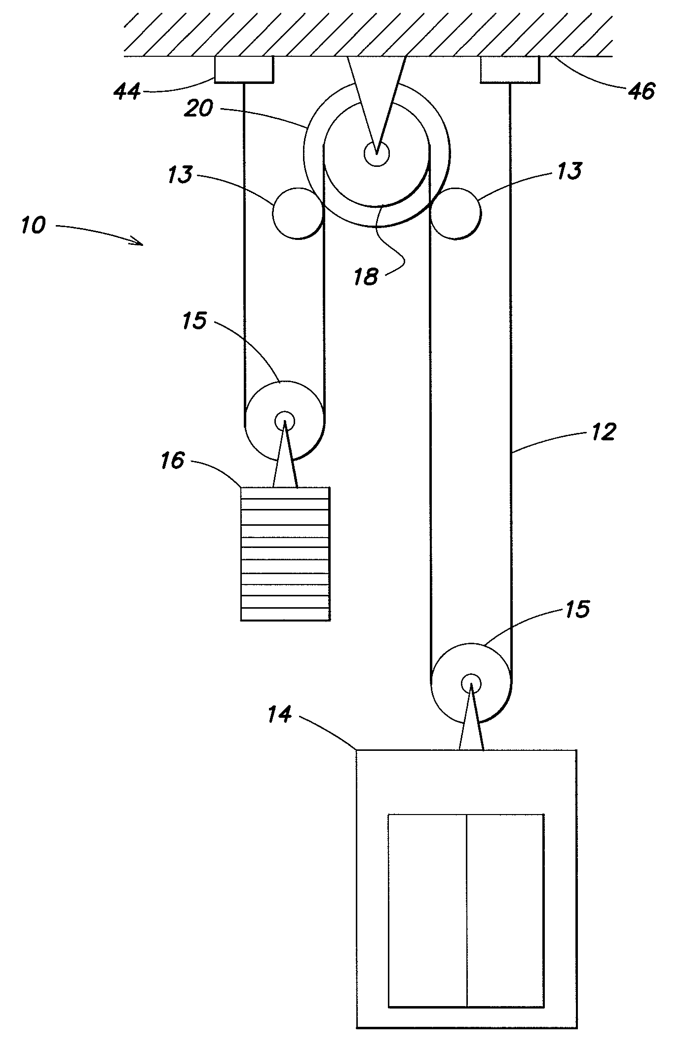
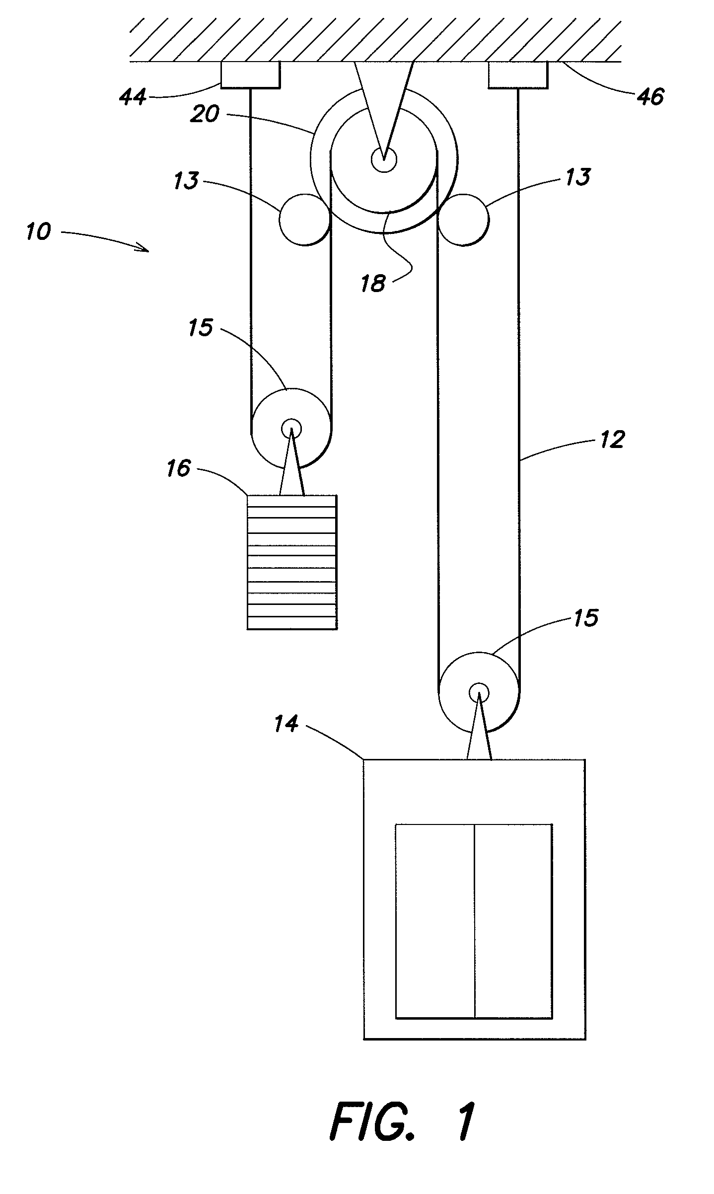
[0024]Now referring to FIG. 1, an elevator system 10 includes an elevator car 14 and a counterweight 16 is diagrammatically shown within a hoistway 46, connected to one another by one or more flexible load-bearing members 12. The load-bearing members 12 are shown extending in a 2:1 roping configuration, wherein the members 12 pass over a drive sheave 18, drop to the elevator car 14 or counterweight 16, and subsequently wrap around another unpowered sheave(s) 15 attached to the respective car 14 or counterweight 16 before returning to an anchor position 44 at the top of the hoistway 46. As will be detailed below, frictional engagement (i.e., traction) between the drive sheave 18 and load-bearing member 12 enables the drive sheave 18 to move the load-bearing member 12 and therefore the attached elevator car 14 and counterweight 16.

[0025]In a 2:1 system, the grooves of the sheaves 15, 18 are typically crowned for alignment purposes, as will be discussed below. The configuration of the ...


PUM


Abstract

A load-bearing member operable to be driven by a drive sheave in an elevator system is provided. The load-bearing member has a body defined by a thickness, a width that is greater than the thickness, and a length. The body comprises a single solid material that is uniform in the cross-section, and is sufficiently flexible to permit the member to wrap at least partially around the drive sheave of an elevator system. An elevator system is also provided that includes the aforesaid load-bearing members, a car, a counterweight and a drive sheave. The load-bearing members connect the car and counterweight to the drive sheave, and are wrapped at least partially around the drive sheave.

Description

CROSS-REFERENCE TO RELATED PATENT APPLICATIONS[0001]This application claims the benefit of U.S. Provisional Patent Application No. 60 / 894,990 filed Mar. 15, 2007, which is incorporated by reference herein in its entirety.BACKGROUND OF THE INVENTION[0002]1. Technical Field[0003]This invention generally relates to elevator systems in general, and to flexible load-bearing members for supporting and propelling an elevator car relative to a drive sheave in particular.[0004]2. Background Information[0005]There are several known types of elevator systems. Traction-based systems typically include an elevator car and a counterweight and load-bearing members that support and connect the car and counterweight. The car is moved between various floors because of friction / traction between the load-bearing members and a drive sheave.[0006]Historically, elevator systems have used “ropes” to extend between an elevator car and a drive sheave, and in some applications to a counterweight as well. The t...

Claims


Application Information

Patent Timeline
Patent Type & Authority Applications(United States)
IPC IPC(8): B66B11/08
CPCB66B7/062
Inventor O'DONNELL, HUGH
Owner ODONNELL HUGH
Why Eureka
Try Eureka