Absolute value scale and absolute value calculating method

a technology of absolute value and absolute value, which is applied in the direction of walking sticks, liquid/fluent solid measurement, instruments, etc., can solve the problems of difficult to obtain stable detection accuracy, detection accuracy, and more likely to affect detection accuracy, so as to increase the space occupied by each coil pattern, easily and reliably calculate the absolute angle and absolute amount of displacement

Inactive Publication Date: 2008-09-18
MITSUBISHI HEAVY IND LTD
View PDF9 Cites 9 Cited by
  • Summary
  • Abstract
  • Description
  • Claims
  • Application Information

AI Technical Summary

Benefits of technology

[0020]The present invention has been made in view of the foregoing problems. An object of the present invention is to provide rotary and linear absolute value scales capable of increasing space occupied by each coil pattern (lengths in a radial directio

Problems solved by technology

As a consequence, detection accuracy is more likely to be affected by manufacturing variation among the absolute value scales, and thus stable detection accuracy is difficult to obta

Method used


Image

  • Absolute value scale and absolute value calculating method
  • Absolute value scale and absolute value calculating method
  • Absolute value scale and absolute value calculating method

Examples


first embodiment

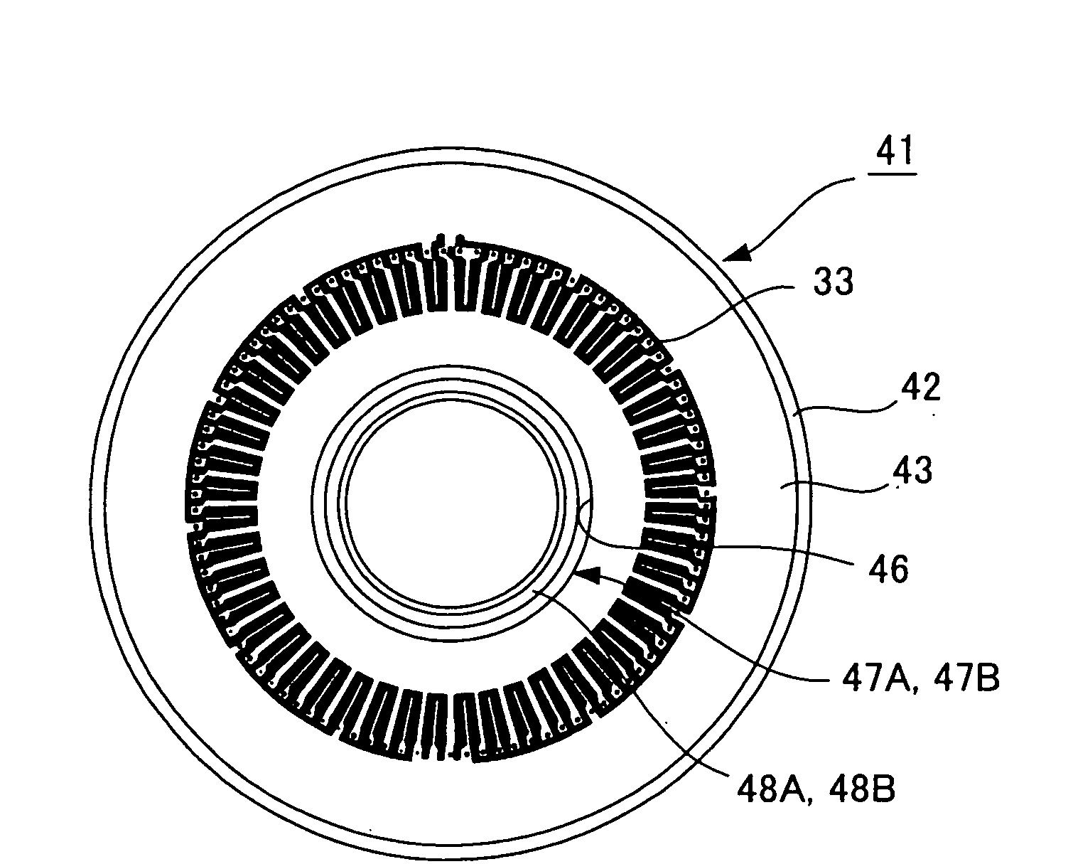
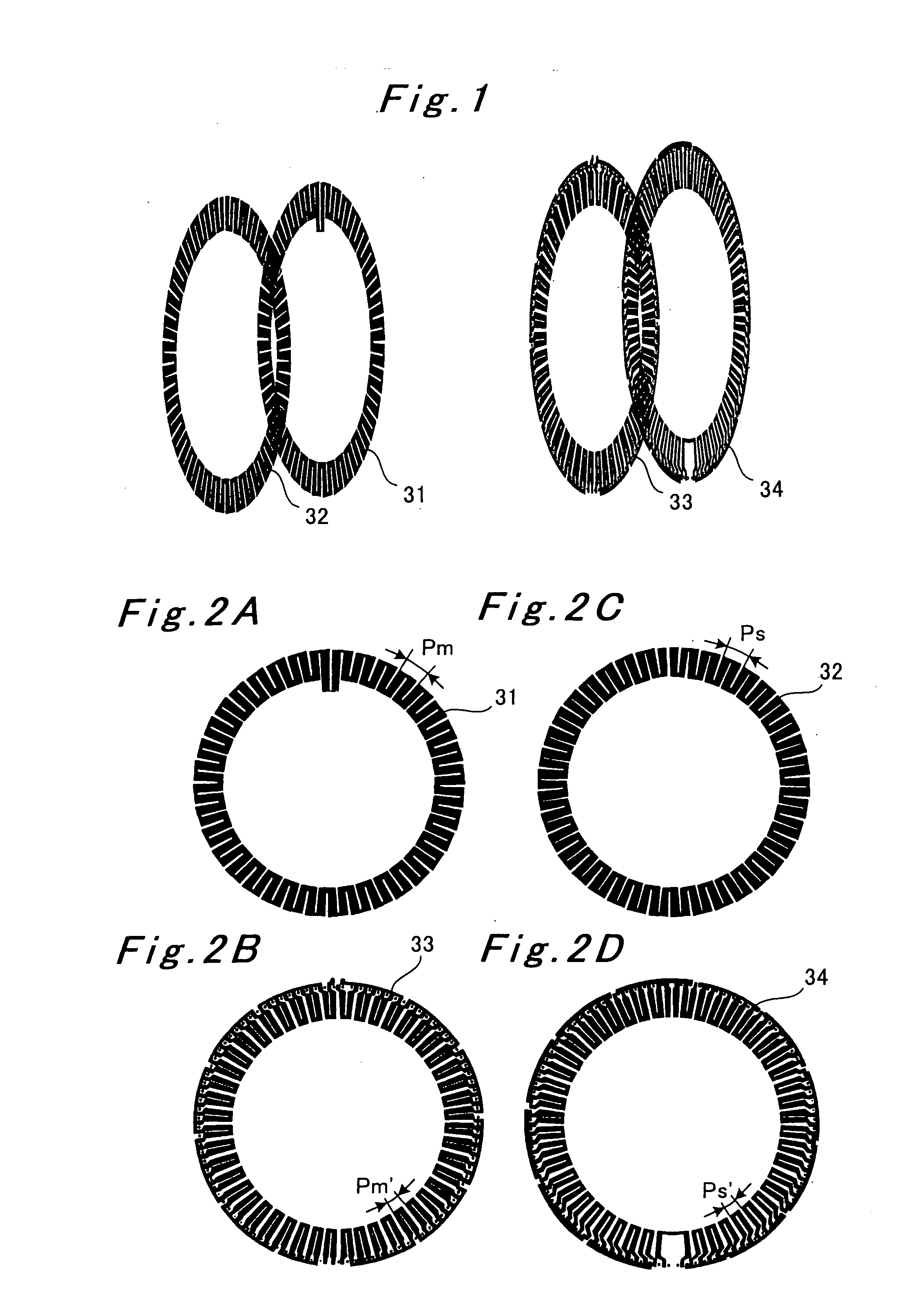
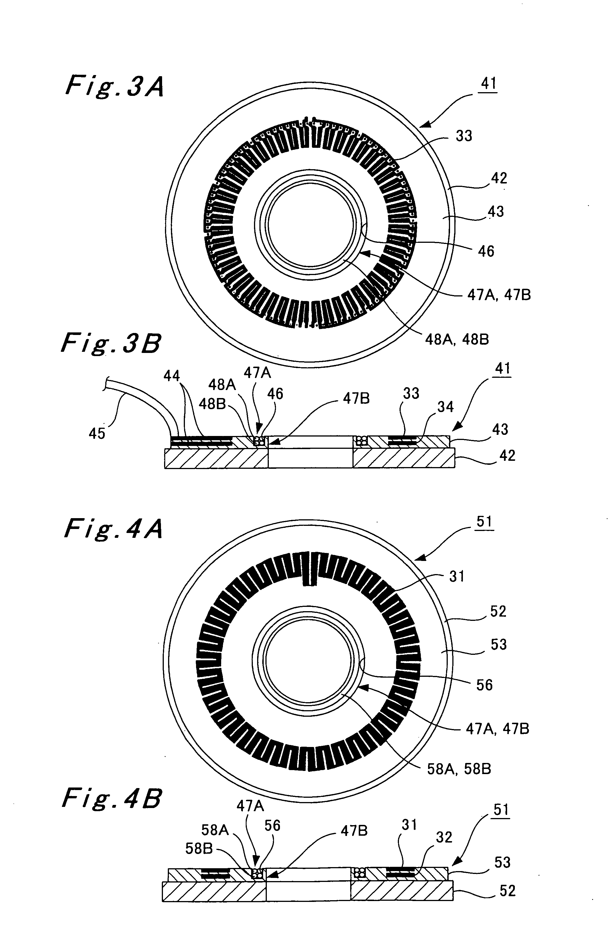
[0075]FIG. 1 is a perspective view of rotor side coil patterns and stator side coil patterns of a rotary absolute value scale according to a first embodiment of the present invention. FIGS. 2A to 2D are front views of the rotor side coil patterns and the stator side coil patterns. FIG. 3A is a front view and FIG. 3B is a sectional side view of a stator constituting the rotary absolute value scale. FIG. 4A is a front view and FIG. 4B is a sectional side view of a rotor constituting the rotary absolute value scale. FIG. 5 is a sectional side view showing an overall configuration of the rotary absolute value scale. FIG. 6 is a diagram showing a circuit configuration of the rotary absolute value scale. FIG. 7 is a diagram showing another circuit configuration of the rotary absolute value scale. FIGS. 8 to 13 are graphs for explaining contents of a process for calculating an absolute angle by use of a scale control device of the rotary absolute value scale.

[0076]The rotary absolute value...

second embodiment

[0119]FIG. 14 is a perspective view of slider side coil patterns and scale side coil patterns of a linear absolute value scale according to a second embodiment of the present invention. FIGS. 15A to 15D are front views of the slider side coil patterns and the scale side coil patterns. FIG. 16A is a front view and FIG. 16B is a sectional side view of a slider constituting the linear absolute value scale. FIG. 17A is a front view and FIG. 17B is a sectional side view of a scale constituting the linear absolute value scale. FIG. 18 is a sectional side view showing an overall configuration of the linear absolute value scale. FIG. 19 is a diagram showing a circuit configuration of the linear absolute value scale. FIG. 20 is a diagram showing another circuit configuration of the linear absolute value scale. FIGS. 21 to 26 are graphs for explaining contents of a process for calculating an absolute value of displacement by use of a scale control device of the linear absolute value scale.

[01...


PUM


Abstract

A rotary absolute value scale includes a rotor in which two rotor side coil patterns provided with different pitches are laminated, and a stator in which two stator side coil patterns provided with different pitches are also laminated. A linear absolute value scale includes a slider in which two slider side coil patterns provided with different pitches are laminated, and a scale in which two scale side coil patterns provided with different pitches are also laminated.

Description

BACKGROUND OF THE INVENTION[0001]1. Field of the Invention[0002]The present invention relates to an inductosyn type absolute value scale and an absolute value calculating method.[0003]2. Description of the Related Art[0004]An inductosyn type scale employed in machine tools and the like includes a rotary type (a rotary scale) and a linear type (a linear scale).[0005]The rotary scale is for detecting a rotation angle, and is configured of: a rotor on a rotating side having a rotor side coil pattern 1 folded in a zigzag manner and formed into an annular shape on the whole as shown in FIG. 27A; and a stator on a fixed side having a stator side coil pattern 2 folded in a zigzag manner and formed into an annular shape on the whole as shown in FIG. 27B. Here, the rotor and the stator are disposed to face each other so that the rotor side coil pattern 1 and the stator side coil pattern 2 can face each other.[0006]In this rotary scale, when an alternating current is supplied to the stator si...

Claims


Application Information

Patent Timeline
IPC IPC(8): G06C27/00
CPCG01D5/2086G01D1/16G01D18/008
Inventor ISHII, KOHTAKEUCHI, KATSUYOSHI
Owner MITSUBISHI HEAVY IND LTD
Why Eureka
Try Eureka