Automatic front feeding device

An automatic feeding, front-end technology, applied in the field of CNC machine tools, can solve the problems of inconsistent length of workpiece, difficult connection processing, low processing efficiency, etc., and achieves the effect of simple structure, small footprint and stable operation.

Active Publication Date: 2014-03-05
GUANGZHOU LONGBANG AUTOMATIC CONTROL EQUIP
View PDF6 Cites 4 Cited by
  • Summary
  • Abstract
  • Description
  • Claims
  • Application Information

AI Technical Summary

Problems solved by technology

[0002] At present, when CNC machine tools process a kind of material, most CNC machine tools are equipped with bar material automatic feeding devices, and these devices are mostly installed at the rear end of the machine tool spindle, and the effect is also very good and the efficiency is very high. However, when it is necessary to process When different short materials or pellets are used, usually due to the inconsistent length and size of the workpieces, it is impossible to realize continuous clamping and processing of different materials. The traditional method is to use almost all manual loading and clamping, and one person can only In the situation of operating one machine tool, the processing efficiency is low, and many operators are required in mass production, which makes it difficult to realize on-line processing

Method used


Image

  • Automatic front feeding device
  • Automatic front feeding device
  • Automatic front feeding device

Examples


Embodiment Construction

[0019] The front-mounted automatic feeding device of the present invention will be described in further detail below in conjunction with the accompanying drawings. It is worth noting that some specific quantities will be involved in this embodiment. No limitation is imposed on the present invention.

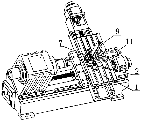
[0020] like figure 1 Shown: a front-type automatic feeding device according to the present invention is installed on the slide table 1 of the machine tool.

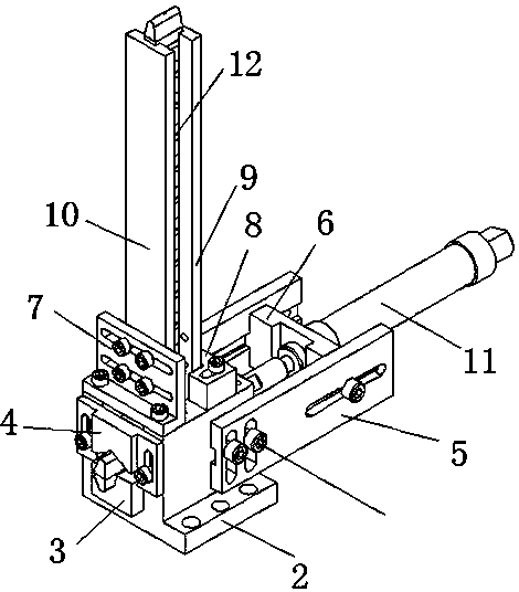
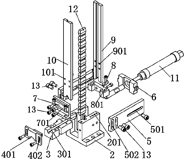
[0021] The specific structure of the front-mounted automatic feeding device is as follows: Figure 1~4 As shown: the bottom of the fixed seat 2 is fixed on the machine tool slide 1, and there is a bracket 3 inside, and an upper bracket 4 is arranged on the upper and rear sides of the bracket 3, and the front and rear sides of the upper surface of the fixed seat behind the upper bracket 4 are respectively fixed The front leakage baffle plate 7 and the rear leakage material baffle plate 8, the front retaining strip 9 and the...


PUM


Abstract

The invention relates to an automatic front feeding device. The automatic front feeding device comprises a fixed base installed on a moving table of a machine tool, wherein a supporting base is installed in the fixed base, a front leaked-material baffle and a rear leaked-material baffle are arranged on the front side and the rear side of the upper surface of the fixed base respectively, a front blocking strip and a rear blocking strip are installed between the front leaked-material baffle and the rear leaked-material baffle, a workpiece is loaded by the front blocking strip and the rear blocking strip, inverted-V-shaped grooves are formed in the bottom of the front blocking strip and the bottom of the rear blocking strip respectively, a first workpiece position is formed above the supporting base, one workpiece can pass through the first workpiece position, fixing plates are installed on the two sides of the fixed base respectively, an air cylinder base is arranged on the inner sides of the fixing plates, an air cylinder is installed in the middle of the air cylinder base, and a push rod of the air cylinder exactly faces the first workpiece position. According to the automatic front feeding device, full-automatic feeding and clamping of short materials and granular materials are achieved, dozens of workpieces can be loaded on the automatic front feeding device at one time, a plurality of machine tools can be operated by one person at the same time, rapid line connection machining is facilitated, and machining efficiency is greatly improved; meanwhile, the automatic front feeding device is small in occupied space, simple in structure, convenient to control, stable in operation and wide in range of application.

Description

technical field [0001] The invention relates to the technical field of numerical control machine tools, in particular to a front-mounted automatic feeding device for conveying short materials or granular materials on a numerical control lathe. Background technique [0002] At present, when CNC machine tools process a kind of work material, most CNC machine tools are equipped with bar material automatic feeding devices, and these devices are mostly installed at the rear end of the machine tool spindle, and the effect is also very good and the efficiency is very high. However, when it is necessary to process When different short materials or pellets are used, usually due to the inconsistent length and size of the workpieces, it is impossible to realize continuous clamping and processing of different materials. The traditional method is almost all manual loading and clamping, and one person can only In the situation of operating one machine tool, the processing efficiency is lo...

Claims


Application Information

Patent Timeline
IPC IPC(8): B23B15/00
CPCB23Q7/006
Inventor 刘芳艺谭习旺蓝方伟
Owner GUANGZHOU LONGBANG AUTOMATIC CONTROL EQUIP
Why Eureka
Try Eureka