Method and apparatus for adjusting orientation direction of array antenna of direction detection apparatus

a technology of array antenna and direction detection apparatus, which is applied in the direction of antenna details, instruments, antennas, etc., can solve the problems of inability to use the vehicle, the direction of detected direction obtained for a stationary target object to vary substantially with time, and it is difficult or impossible to perform the adjustment to a sufficiently high degree of accuracy. , to achieve the effect of accurate adjustmen

Active Publication Date: 2008-09-18
DENSO CORP
View PDF3 Cites 16 Cited by
  • Summary
  • Abstract
  • Description
  • Claims
  • Application Information

AI Technical Summary

Benefits of technology

[0027]It is an objective of the present invention to overcome the above problems by providing a method and apparatus for enabling the orientation direction of an array antenna of a direction detection apparatus to be accurately adjusted in relation to a specific coordinate system.
[0028]To achieve the above objectives, the invention provides a method of adjusting the orientation direction of an array antenna, which is applicable to a direction detection apparatus that transmits radar waves, receives resultant reflected incident waves from one or more target objects, estimates the total number of these target objects, and calculates respective directions of the incident waves (i.e., representing respective directions of the target objects) based on the assumption that the estimated number of incident wave directions is correct. To adjust the array antenna orientation direction, one or more target objects (in general, a single target object, i.e., radar reflector) are disposed at respective predetermined directions from the array antenna, and (when set in an antenna adjustment mode of operation) the direction detection apparatus is controlled to calculate the incident wave directions based on the actual known number of target objects, rather than on an estimated number. In that way, stable calculation of the incident wave directions can be achieved by the apparatus, free from time axis variations in the detected directions, so that the amount of deviation between the detected directions and the actual directions can be accurately obtained. Hence, the angular position of the array antenna can be quickly and accurately adjusted to bring the amount of deviation to zero, thereby accurately adjusting the orientation direction of the antenna.
[0029]Preferably, a single target object (radar reflector) is used for performing such adjustment, with the reflector being disposed at a direction from the array antenna that corresponds to the reference (0°) direction of the antenna. In that case, information expressing the incident wave direction obtained by the direction detection apparatus can be monitored by a user while performing adjustment of the array antenna orientation. The user can thereby readily determine the extent to which the calculated incident wave direction differs from the reference direction. The angular position of the array antenna can thus be adjusted to bring that extent of difference towards zero.
[0030]The advantages of the invention are based upon the fact that the aforementioned fluctuations which occur with time, for the detected direction of a target object, can be substantially entirely eliminated if the direction detection apparatus calculates the direction of the target object on the basis that there is only a single target object, rather than deriving an estimated number of potential target objects and performing direction calculations based on the assumption of that estimated number of target objects.
[0031]Hence, a displayed amount of deviation of a detected direction from the actual direction of a target object, when observed by a user, can be utilized by the user to accurately adjust the array antenna orientation.
[0036]The invention is for example applicable to a direction detection apparatus that is mounted on a vehicle, for detecting the directions of target objects that are located ahead of the vehicle. In that case, the orientation direction of the array antenna can be accurately adjusted in relation to a coordinate system that is defined by the body of the vehicle.

Problems solved by technology

If the relationship between this coordinate system and the vehicle position coordinates is not fixedly predetermined, then it is not possible to use the vehicle as a reference for evaluating the detected position and direction, etc., of a target object, in order to control the vehicle in accordance with such detection information.
However in practice, the direction detection results that are obtained from such a type of apparatus are affected by factors such as electrical noise, etc., causing the detected direction obtained for a stationary target object to vary substantially with time.
Hence the problem arises with such an adjustment method that, if the antenna orientation is adjusted while observing the direction detection results (i.e., to attempt to adjust the detected direction to coincide with the actual known direction of a target object such as a radar reflector), it is difficult or impossible to perform the adjustment to a sufficiently high degree of accuracy.

Method used


Image

  • Method and apparatus for adjusting orientation direction of array antenna of direction detection apparatus
  • Method and apparatus for adjusting orientation direction of array antenna of direction detection apparatus
  • Method and apparatus for adjusting orientation direction of array antenna of direction detection apparatus

Examples


Embodiment Construction

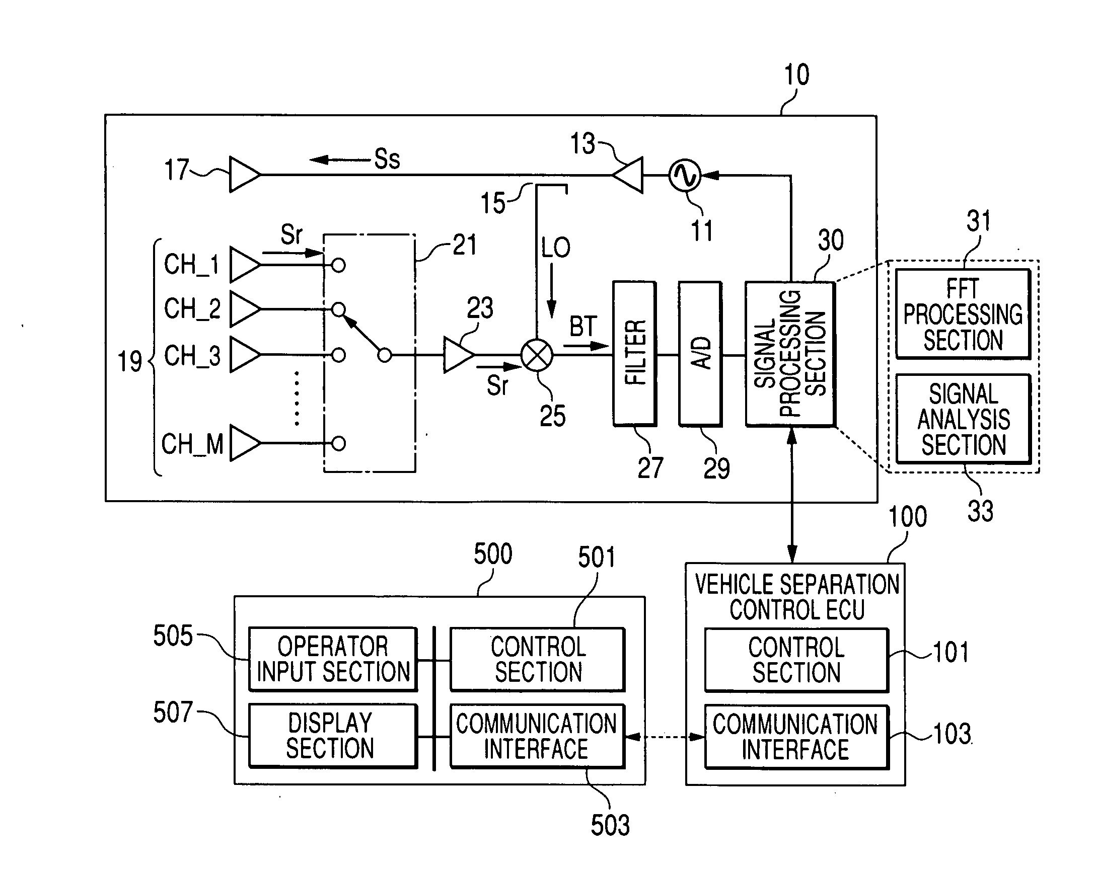
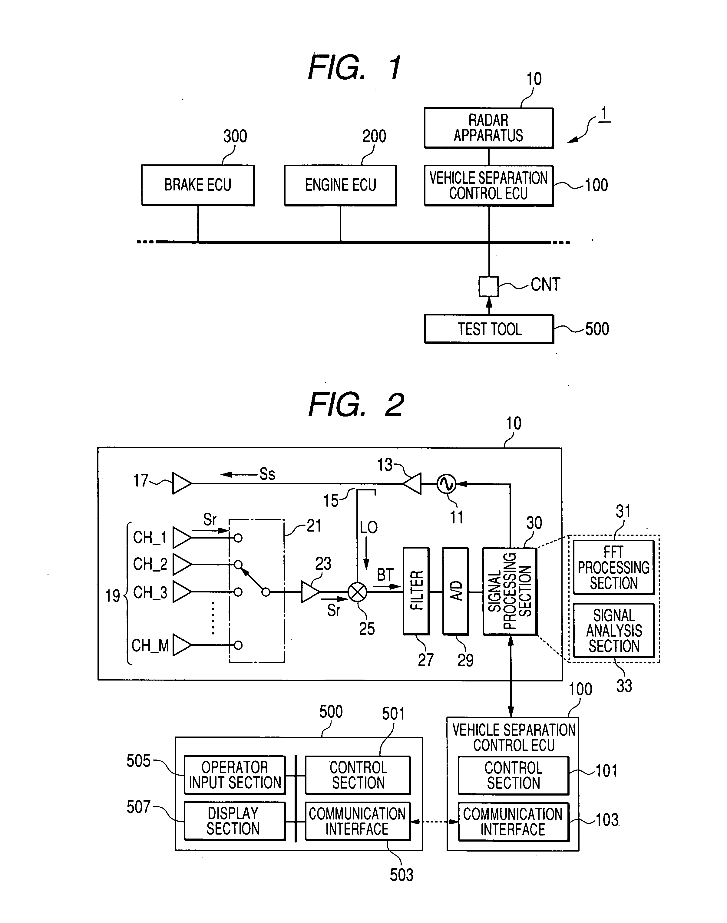
[0047]An embodiment of an apparatus utilizing an antenna orientation adjustment method according to the present invention will be described in the following, referring first to FIGS. 1 and 2. FIG. 1 is a general block diagram of a vehicle control system 1, which includes a vehicle separation control ECU 100, a engine ECU 200, and a brake ECU 300, which incorporate respective ECUs (electronic control units) which communicate via a in-vehicle LAN (local area network). Each of the ECUs is based on a microcomputer and a communication interface for performing communication with other ECUs that are connected to the LAN, to execute processing sequences in cooperation with the other ECUs.

[0048]The vehicle separation control ECU 100 is connected to a radar apparatus 10, with details of the vehicle separation control ECU 100 and radar apparatus 10 being shown in FIG. 2. As shown, the vehicle separation control ECU 100 includes a control section 101 and a communication interface 103. As descri...


PUM


Abstract

A direction detection apparatus transmits radar waves, with resultant reflected waves being received as incident waves by elements of an array antenna. Normally the direction of a target object is calculated based on analyzing respective received signals from the antenna elements, in calculations utilizing an estimated total number of incident wave directions. In an antenna direction adjustment mode, an actual number of target objects, and hence actual number of incident wave directions, is utilized in place of the estimated value, thereby enabling direction detection information to be obtained which does not fluctuate with time, thus facilitating the adjustment.

Description

CROSS-REFERENCE TO RELATED APPLICATIONS[0001]This application is based on and incorporates herein by reference Japanese Patent Application No. 2006-330749 filed on Dec. 7, 2006.BACKGROUND OF THE INVENTION[0002]1. Field of Application[0003]The present invention relates to a method and apparatus for adjusting the orientation direction of an array antenna of a direction detection apparatus which transmits radar waves.[0004]2. Description of Related Art[0005]Types of direction detection apparatus are known in which radar waves are transmitted, to be reflected from objects located ahead of the apparatus (with such objects referred to in the following as target objects), and thereby returned to the direction detection apparatus as reflected incident waves that are received as signals by an array antenna. The array antenna is formed of a plurality of antenna elements, and the direction detection apparatus estimates the total number of these target objects, and calculates the respective dir...

Claims


Application Information

Patent Timeline
Patent Type & Authority Applications(United States)
IPC IPC(8): G01S13/00H01Q3/00G01S13/931
CPCG01S7/4026G01S13/34G01S13/584G01S13/931H01Q1/3233G01S2013/9375G01S2007/4086G01S2013/9339G01S2013/9346G01S2013/9353H01Q3/24G01S2013/93185G01S2013/9329G01S2013/932G01S2013/93271G01S7/4086
Inventor SHIMIZU, KOJI
Owner DENSO CORP
Why Eureka
Try Eureka