Electronic Timepiece with Generator Function

a technology of generator function and electronic timepiece, which is applied in the direction of electric winding, instruments, horology, etc., can solve the problems of insufficient power generation, secondary battery may not be sufficiently charged, and user is unable to confirm whether the current power generator is producing sufficient power, etc., to achieve simple arrangement and easy determination of power generating state

Inactive Publication Date: 2008-09-18
SEIKO EPSON CORP
View PDF9 Cites 7 Cited by
  • Summary
  • Abstract
  • Description
  • Claims
  • Application Information

AI Technical Summary

Benefits of technology

[0014]Because this aspect of the invention has a power generation detection means that detects power generation, and a power generation display means that displays the power generation state based on a detection result signal output from the power generation detection means, the timepiece user can confirm power generation by the generating means in real time, and easily confirm whether sufficient power has been generated. If sufficient power has not been generated, the user can take appropriate action to increase generation and reliably generate sufficient power.
[0065]The electronic timepiece with a power generating means according to the present invention has the effect of enabling the user to easily determine the power generating state of the power generator.

Problems solved by technology

While the prior art can thus detect the voltage and remaining capacity of the secondary battery, the user is unable to confirm whether the power generator is currently producing sufficient power.
This means that if the timepiece has a manual power generator that produces electricity as a result of the user turning the crown of the timepiece, for example, the secondary battery may not be sufficiently charged because the user does not know whether if sufficient power has been produced.
More specifically, when the crown of the timepiece is wound to drive the rotor of the power generator so that the magnetic flux crossing the coil as a result of rotor rotation changes, power cannot be sufficiently generated unless the rotor turns at a sufficiently high speed.
This means that the secondary battery may not be sufficiently charged no matter how long the crown is turned if the user winds the crown slowly.

Method used


Image

  • Electronic Timepiece with Generator Function
  • Electronic Timepiece with Generator Function
  • Electronic Timepiece with Generator Function

Examples


Embodiment Construction

[0078]Preferred embodiments of the present invention are described below with reference to the accompanying figures.

[0079]General Configuration of an Electronic Timepiece

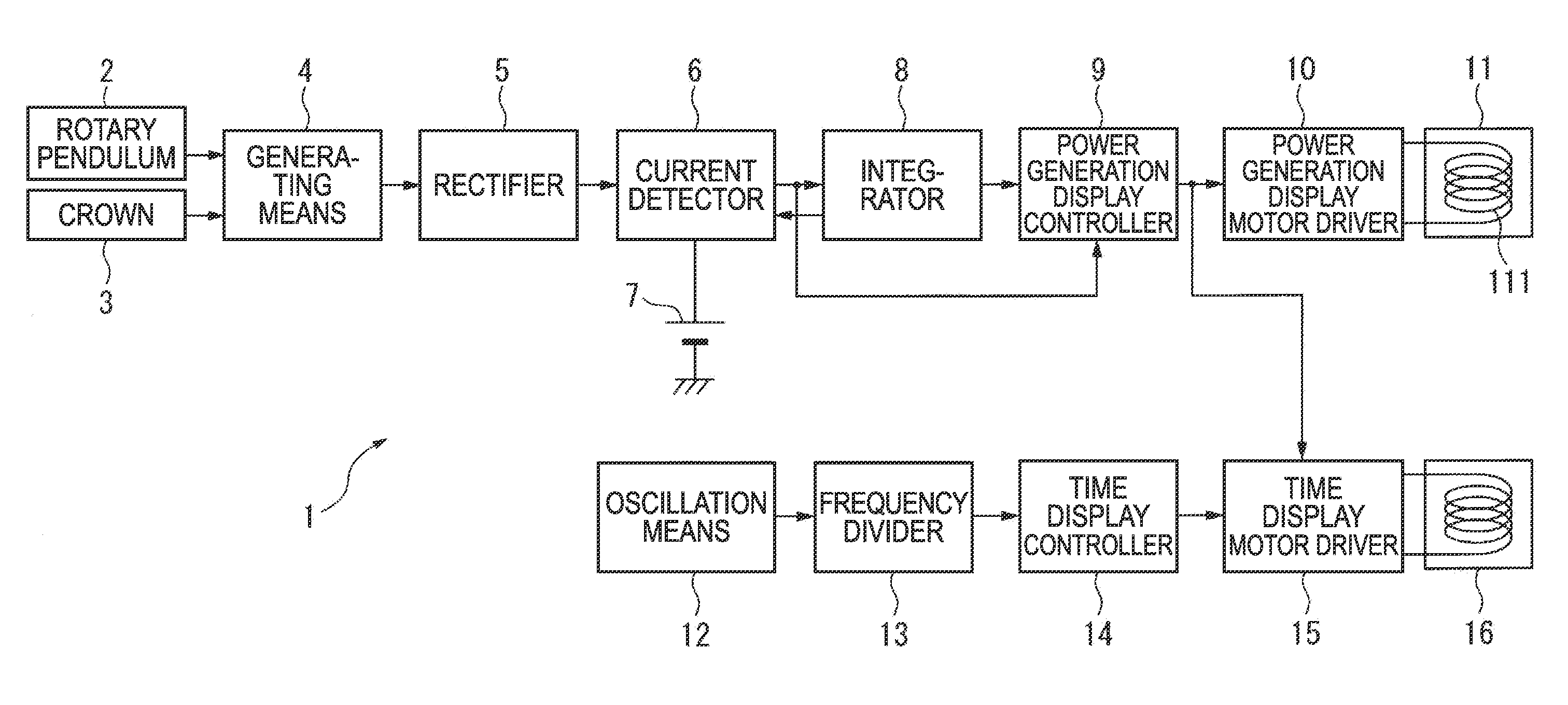
[0080]As shown in FIG. 1, an electronic timepiece 1 according to the present invention has a rotary pendulum 2, a crown 3, a generating means 4, a rectification means 5, a current detection means 6, a secondary battery 7 as a power storage means, an integration means 8, a power generation display control means 9, a power generation display motor driving means 10, a power generation display motor 11, an oscillation means 12, a frequency division means 13, a time display control means 14, a time display motor driving means 15, and a time display motor 16.

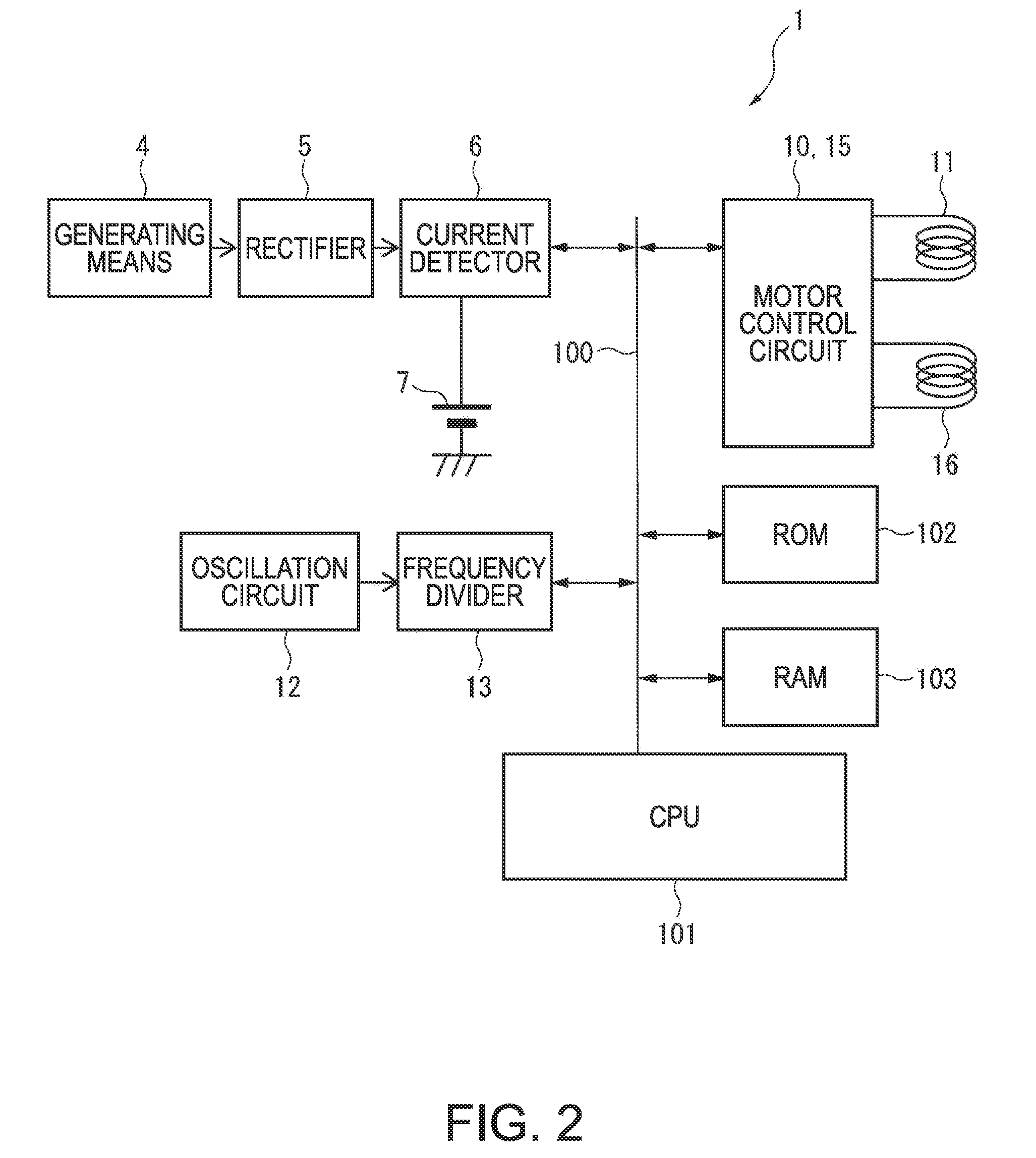
[0081]As shown in the hardware schematic in FIG. 2, the current detector 6 (current detection circuit), frequency divider 13 (frequency division circuit), and the motor drive means 10 and 15 (motor control circuits) are connected to a CPU 101 (central processing unit)...


PUM


Abstract

An electronic timepiece with a generator function, including a generating means, a storage means that stores electrical energy produced by the generating means, a timekeeping control means that is driven by the electrical energy stored in the storage means, a time display means that is controlled by the timekeeping control means and displays time, a power generation detection means that detects the power generation state of the generating means, and a power generation display means that displays the power generation state based on a detection result signal output from the power generation detection means. The power generation detection means includes a hand and an actuator that drives the hand in both forward and reverse directions.

Description

CROSS-REFERENCE TO RELATED APPLICATIONS[0001]Japanese Patent application No. 2007-065646 is hereby incorporated by reference in its entirety. This application is also related to application Ser. No. ______, (Attorney Docket No. P134853a) filed ______.BACKGROUND[0002]1. Field of Invention[0003]The present invention relates to an electronic timepiece with a power generator function.[0004]2. Description of Related Art[0005]Replacing the battery is not necessary with timepieces that have a power generator function, and such timepieces have therefore come into widespread use.[0006]Electronic timepieces with a power generator function store the power produced by the power generator in a secondary battery for use. Japanese Examined Patent Pub. JP-A-S61-61077 teaches a timepiece that has a function for indicating the remaining operating time to the timepiece user, and detecting and displaying how much voltage is left in the secondary battery in order to initiate recharging as may be require...

Claims


Application Information

Patent Timeline
Patent Type & Authority Applications(United States)
IPC IPC(8): G04B9/00G04C3/00G04C10/00
CPCG04C10/04
Inventor KAWAGUCHI, TAKASHI
Owner SEIKO EPSON CORP
Why Eureka
Try Eureka