Data recovery method, image processing apparatus, controller board, and data recovery program
- Summary
- Abstract
- Description
- Claims
- Application Information
AI Technical Summary
Benefits of technology
Problems solved by technology
Method used
Image
Examples
embodiment 1
[0078]FIGS. 6A and 6B show conceptual diagrams illustrating a data recovery method according to an embodiment of the invention. FIG. 6A shows the multifunction peripheral 100 prior to replacement of the controller board 101. FIG. 6B shows the multifunction peripheral 100 after replacement of the controller board 101.
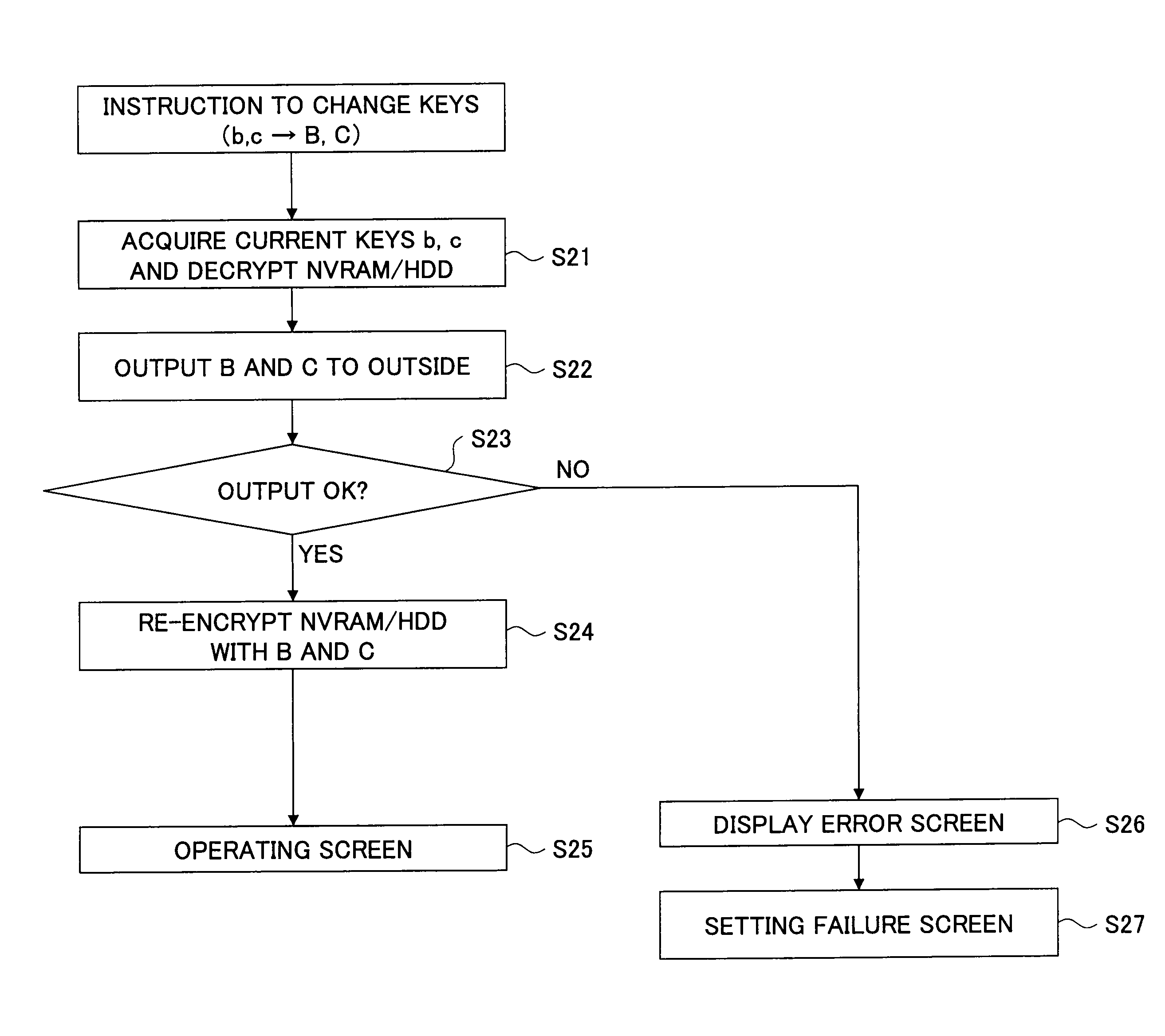
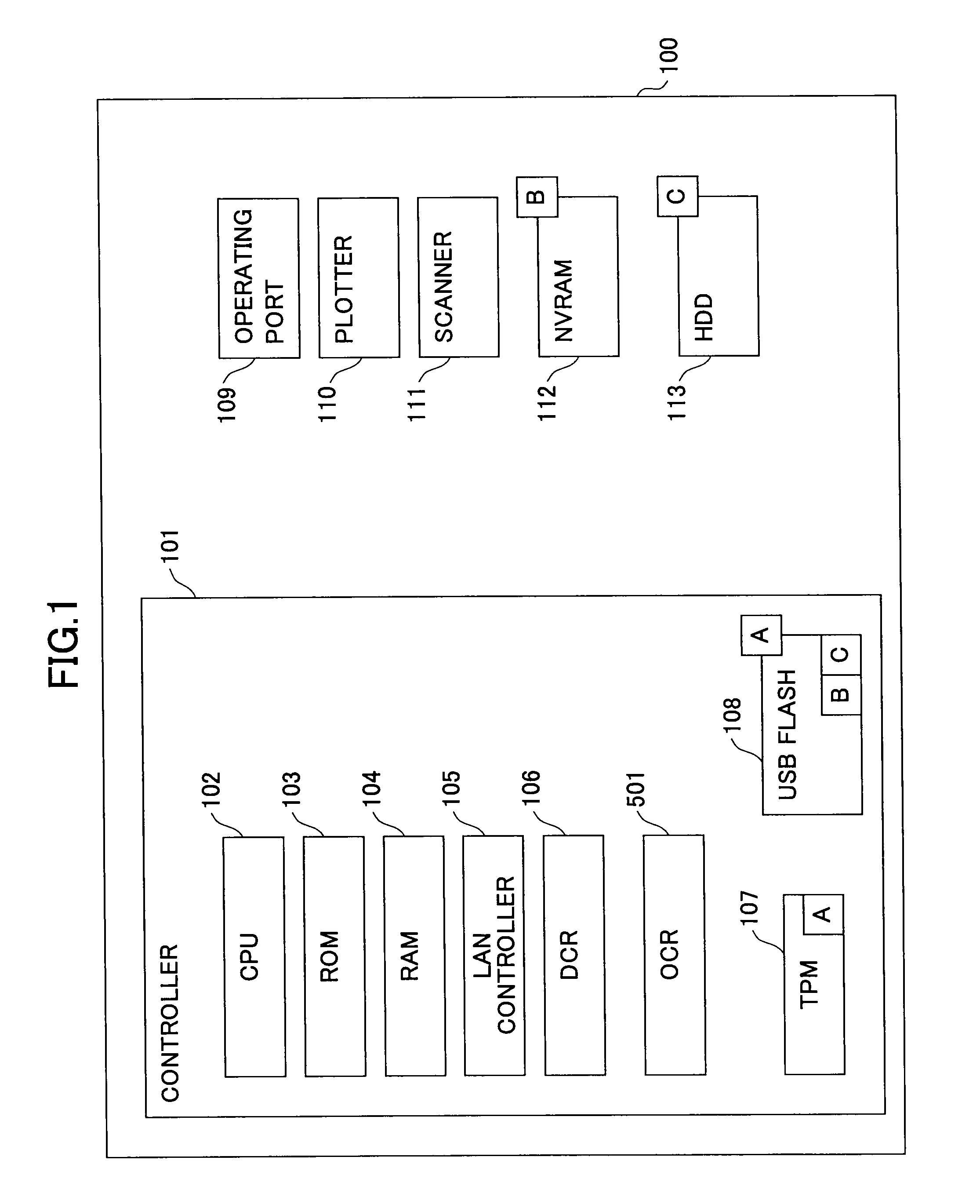
[0079]In the multifunction peripheral 100 of the present embodiment, the encryption keys B and C saved in the USB flash memory 108 are output to the outside of the multifunction peripheral 100 via the operating panel or the like while the controller board 101 is normally operating. After replacement of the controller board 101, the encryption keys B and C that have been placed outside the multifunction peripheral 100 are brought back into the multifunction peripheral 100 via the operating panel or the like, in order to restore the encryption keys B and C back into the USB flash memory 108.
[0080]Thus, in accordance with the multifunction peripheral 100 of the present embo...
embodiment 2
[0108]While it has been described above that the encryption keys B and C are stored in the USB flash memory 108 as encrypted with the encryption key A, another embodiment as shown in FIG. 13 may be employed. FIG. 13 shows a conceptual diagram illustrating the location of storage of the encryption keys. In the example shown in FIG. 13, an encryption key C for the HDD 113 that has been encrypted with the encryption key B is stored in the NVRAM 112.
[0109]Thus, in the multifunction peripheral 100 of the present embodiment, it is possible to store an encryption key for one of plural storage devices in another one of the storage devices that is secure and the most reliable, in an encrypted manner. By storing the encryption key C in the NVRAM 112 for the HDD 113 encrypted with the encryption key B, the need for backing up the encryption key C in the multifunction peripheral 100 can be eliminated.
[0110]While FIG. 13 shows the multifunction peripheral 100 in which the encryption key C for th...
embodiment 3
[0125]FIGS. 17A and 17B show conceptual diagrams illustrating a data recovery method according to another embodiment. FIG. 17A shows the multifunction peripheral 100 prior to replacement of the controller board 101. FIG. 17B shows the multifunction peripheral 100 after replacement of the controller board 101.
[0126]In the multifunction peripheral 100, the encryption keys B and C that are stored in the USB flash memory 108 are saved in an external medium 119, which may be an SD card or a USB memory, while the controller board 101 is normally operating. When storing the encryption keys B and C, the multifunction peripheral 100 asks the user to enter restoration passwords for the encryption keys B and C and encrypts the encryption keys B and C with them.
[0127]After replacement of the controller board 101, the multifunction peripheral 100 restores the encryption keys B and C saved in the external medium 119 by decrypting them with their restoration passwords entered by the user. While FI...
PUM
 Abstract
Description
Claims
Application Information
 - R&D
- Intellectual Property
- Life Sciences
- Materials
- Tech Scout
- Unparalleled Data Quality
- Higher Quality Content
- 60% Fewer Hallucinations
Browse by: Latest US Patents, China's latest patents, Technical Efficacy Thesaurus, Application Domain, Technology Topic, Popular Technical Reports.
© 2025 PatSnap. All rights reserved.Legal|Privacy policy|Modern Slavery Act Transparency Statement|Sitemap|About US| Contact US: help@patsnap.com


