Multi-Stage Trochoidal Vacuum Pump

Inactive Publication Date: 2008-09-18
ION METRICS
View PDF52 Cites 30 Cited by
  • Summary
  • Abstract
  • Description
  • Claims
  • Application Information

AI Technical Summary

Benefits of technology

[0014]In preferred embodiments, the first rotor is positioned between a first cover and a second cover within the first cavity and rotates in a plane parallel to the first cover and the second cover. The first rotor has a first face proximate to and spaced apart from the first cover and has a second face proximate to and

Problems solved by technology

A mass spectrometer can be maintained at high vacuum by suitable pumps; however, the problem of sample introduction from an elevated pressure to a vacuum pressure usually requires substantial flow.
This requirement causes the pumping problem to be difficult with respect to the power needed and the wide dynamic range of the pressures.
Usually, the commercially available pumps are very large and heavy and have a capacity that is more than is necessary for a miniature device.
Although additional pumping capacity may

Method used


Image

  • Multi-Stage Trochoidal Vacuum Pump
  • Multi-Stage Trochoidal Vacuum Pump
  • Multi-Stage Trochoidal Vacuum Pump

Examples


Embodiment Construction

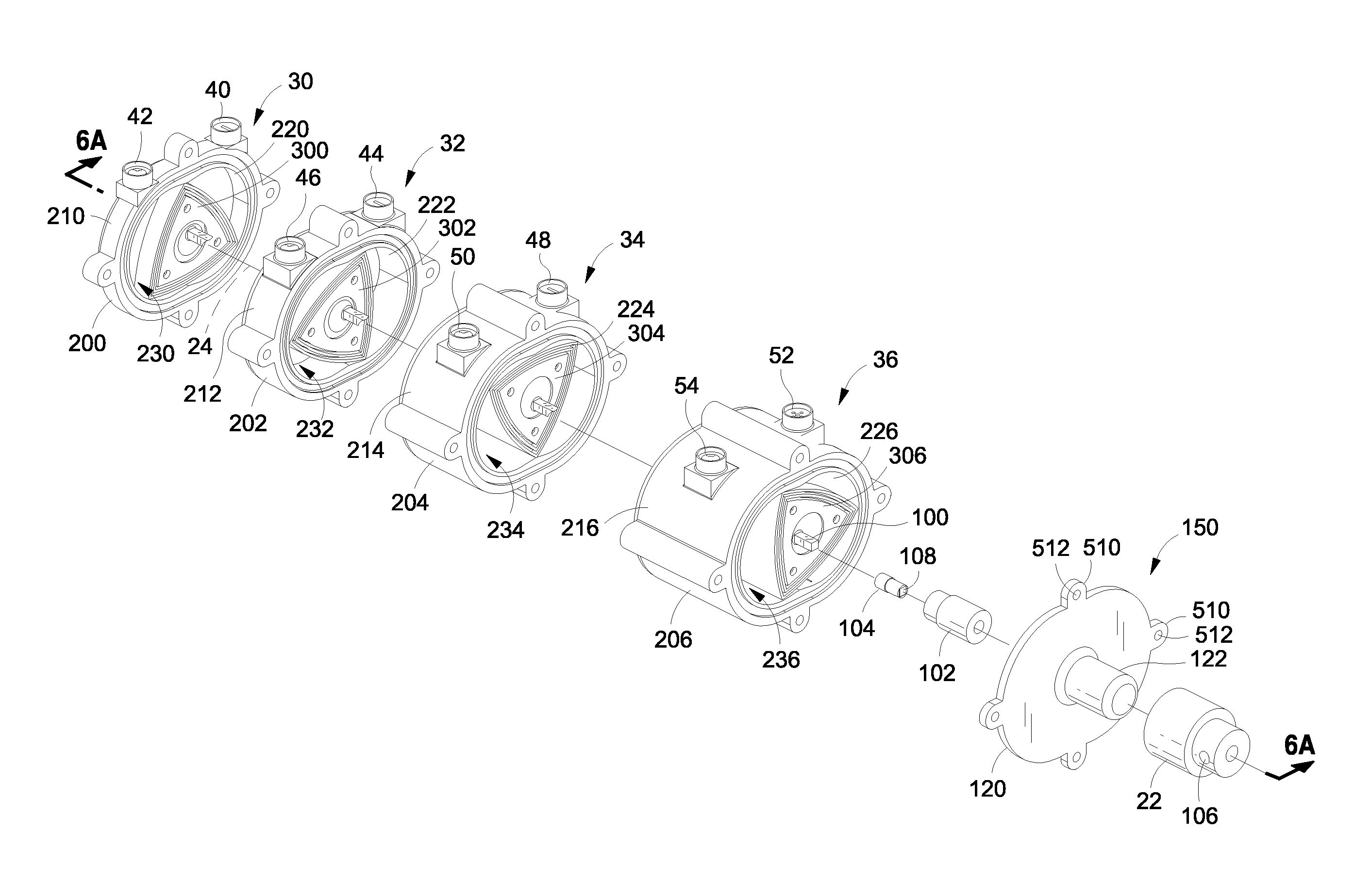
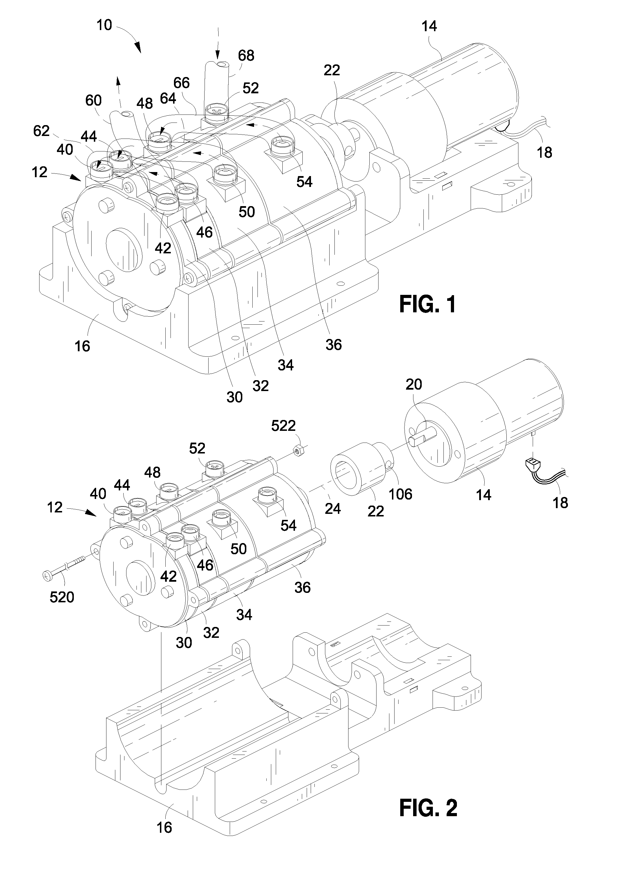
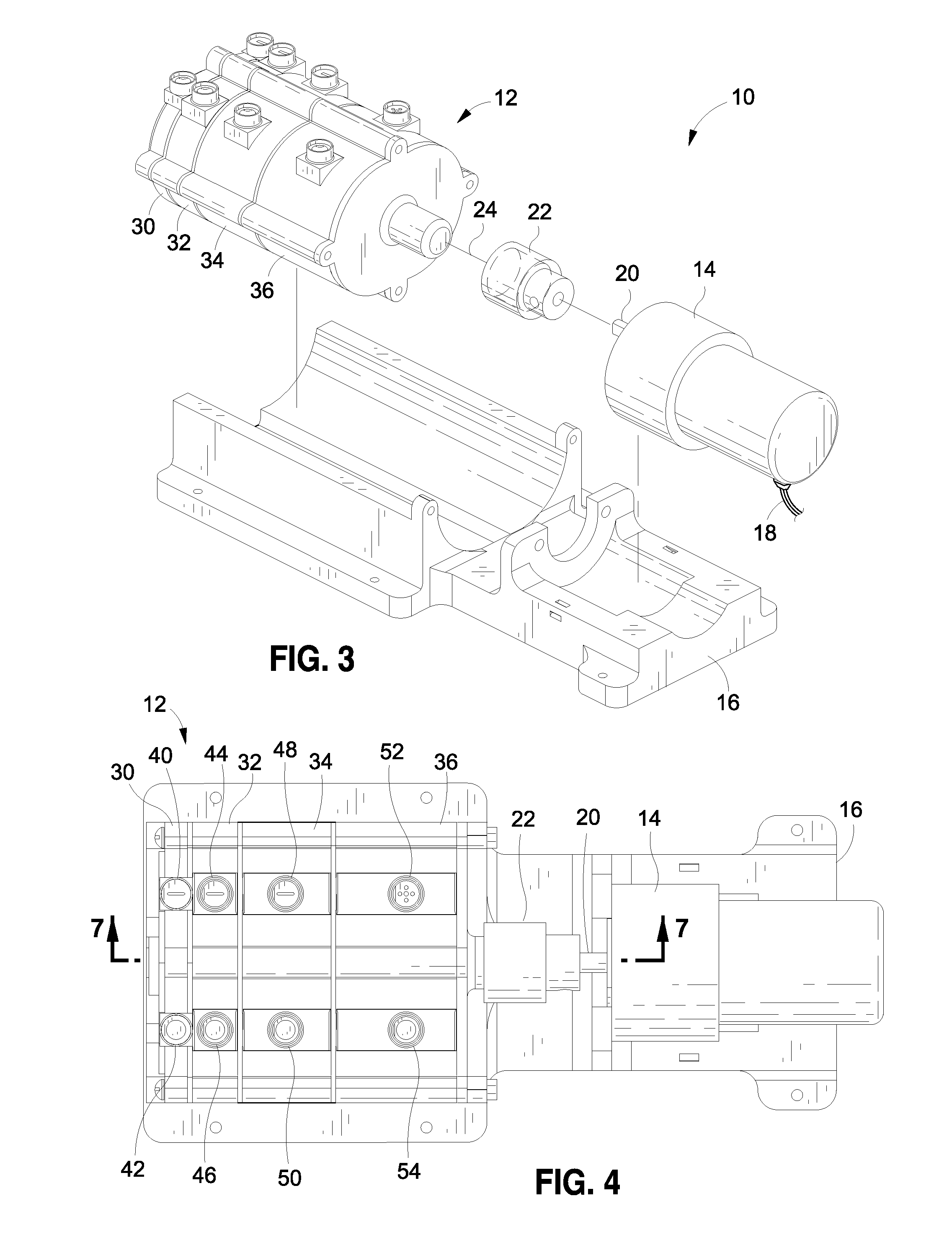
[0050]FIGS. 1-7 illustrate a multi-stage vacuum pump 10 comprising a four-stage pump assembly 12 and a motor 14 mounted on a common platform (or base) 16. The motor receives power from a DC power source (not shown) via a power connection 18. The motor has an output shaft 20 that provides rotational power to the pump assembly via an output coupler 22. The output shaft and the output coupler rotate about a rotational axis 24.

[0051]The four-stage pump assembly 12 comprises a first pump stage 30, a second pump stage 32, a third pump stage 34 and a fourth pump stage 36. The first pump stage is an exhaust stage. The fourth pump stage is an intake stage. The second pump stage and the third pump stage are intermediate stages. In the illustrated embodiment, the fourth pump stage is mounted closest to the motor, and the first pump stage is mounted farthest from the motor; however, the positions of the pump stages can be varied in other embodiments.

[0052]The first pump stage 30 has an input po...


PUM


Abstract

A vacuum pump includes first, second, third and fourth pump stages. Each pump stage has a trochoidal-shaped cavity and a rotor that rotates within the respective cavity. Each cavity has a volume determined by the depth of the cavity and a generally corresponding thickness of the rotor. The fourth stage has a largest volume and receives gas at an input pressure. The fourth stage outputs the gas to the third stage at a second pressure higher than the input pressure. The cavity of each successive stage (third, second and first) has a smaller volume and outputs the gas at a higher pressure than the previous stage. The last (first) stage outputs the gas to the atmosphere. The rotors in the stages rotate about a common pump shaft. Each rotor has a multiple vertices that follow the inner perimeter surface of the respective cavity without contact and without requiring additional seals.

Description

RELATED APPLICATIONS[0001]The present application claims the benefit of priority under 35 USC § 119(e) to U.S. Provisional Application No. 60 / 894,914, filed on Mar. 15, 2007.BACKGROUND OF THE INVENTION[0002]1. Field of the Invention[0003]The present invention is generally in the field of vacuum pumps for removing gases from a system.[0004]2. Description of the Related Art[0005]A mass spectrometer can be maintained at high vacuum by suitable pumps; however, the problem of sample introduction from an elevated pressure to a vacuum pressure usually requires substantial flow. This requirement causes the pumping problem to be difficult with respect to the power needed and the wide dynamic range of the pressures. Often, pumping over a wide dynamic range is accomplished with many pump stages. The pump stages may all operate on the same principle or different stages may operate on different principles. The stages may all be in a common housing or the stages may be in separate housings. Many ...

Claims


Application Information

Patent Timeline
IPC IPC(8): F04C2/02
CPCF04C18/22F04C2220/10F04C23/001
Inventor FERRAN, ROBERT J.OSWALD, MICHAELCORBIN, STEPHEN J.
Owner ION METRICS
Why Eureka
Try Eureka