Eureka AIR delivers breakthrough ideas for toughest innovation challenges, trusted by R&D personnel around the world.

Amphibious all-terrain vehicle

a technology of amphibious motor vehicles and all-terrain vehicles, which is applied in the direction of motor-driven power plants, marine propulsion, vessel construction, etc., can solve the problems of a single operator's inability to effectively drive the vehicle out of water, the seal around the mechanism or the mechanism tends to fail, and the problem of a variety of problems that plague known devices

Inactive Publication Date: 2008-09-18
HYDRATREK IP
View PDF14 Cites 9 Cited by
  • Summary
  • Abstract
  • Description
  • Claims
  • Application Information

AI Technical Summary

Benefits of technology

[0025]The present invention additionally includes a pair of novel hydraulic manifold assemblies that allows the vehicle to be controlled by a single set of controls while being operated in three distinct modes: land drive only; land and water drives simultaneously; and water drive only. The hydraulic manifold assemblies utilize mechanically actuated ball valves to select the vehicle's operational mode and isolates the propeller motors from high pressure when the vehicle is operated in land drive only mode. Moreover, the operator controls the valves in the manifold assemblies using two levers connected by cables to a pair of yokes that actuate the valves on the manifold assemblies. This eliminates the need to use expensive, electrically actuated valves that tend to create problems in high pressure systems due to increased pressure drops and unexpected changes in state due to a Bernoulli effect.

Problems solved by technology

The complexity of designing a vehicle that can operate effectively on all terrain and easily traverse from land operation to water operation and back has lead to a variety of problems that plague known devices.
One problem in known devices is that the drive mechanism, or mechanisms, for the wheels passes through the shell of the vehicle beneath the waterline.
Thus, as the drive mechanism is stressed through torque applied by the power source and through vibration and impact as the vehicle traverses uneven ground, the seal around the mechanism, or mechanisms, tends to fail, allowing water into the passenger compartment.
A second problem is the use of drive systems that utilize a single motor to drive all of the wheels on a single side of the vehicle through complex, failure-prone mechanical systems such as the chain-and-sprocket drive system disclosed in U.S. Pat. No. 3,385,255.
A third problem is the fact that known vehicles that utilize a water propulsion system in addition to their drive wheels either require a separate set of controls for the ground and water propulsion mechanisms or, when a single set of controls is used, drive the wheels simultaneously with the water propulsion mechanism.
The first situation is a problem because it makes it difficult for a single operator to drive the vehicle out of water effectively because this feat generally requires the operator to coordinate the drive systems such that water propulsion system provides sufficient forward force to allow the wheels to engage with the ground forming the bottom of the body of water without slipping.
The second situation is a problem because it siphons power from the water propulsion system and because the rotation of the tires in the water creates drag.
A fourth problem is that the utilization of a single hydraulic system to drive wheel motors and a propeller motor can result subjecting the propeller motor to high pressure when the vehicle is operated in wheels only mode.
This can result in a significant drop in performance of the vehicle because hydraulic motors suitable for providing the high RPM output necessary to drive a propeller are typically of the case drain design such as the PGM-330 from Parker Hannifin Corporation.
If such a case drain type motor is subjected to high pressure and not allowed to rotate, a leakage through the case drain can occur resulting in a significant loss in performance.
A fifth problem is the complexity and cost of building a vehicle with independent hydraulic systems to control both land and water propulsion motors on the left and right sides of the vehicle that can be operated in three distinct modes—land drive only, land and water drive, and water drive only—using single set of controls.

Method used


Image

  • Amphibious all-terrain vehicle
  • Amphibious all-terrain vehicle
  • Amphibious all-terrain vehicle

Examples


Embodiment Construction

)

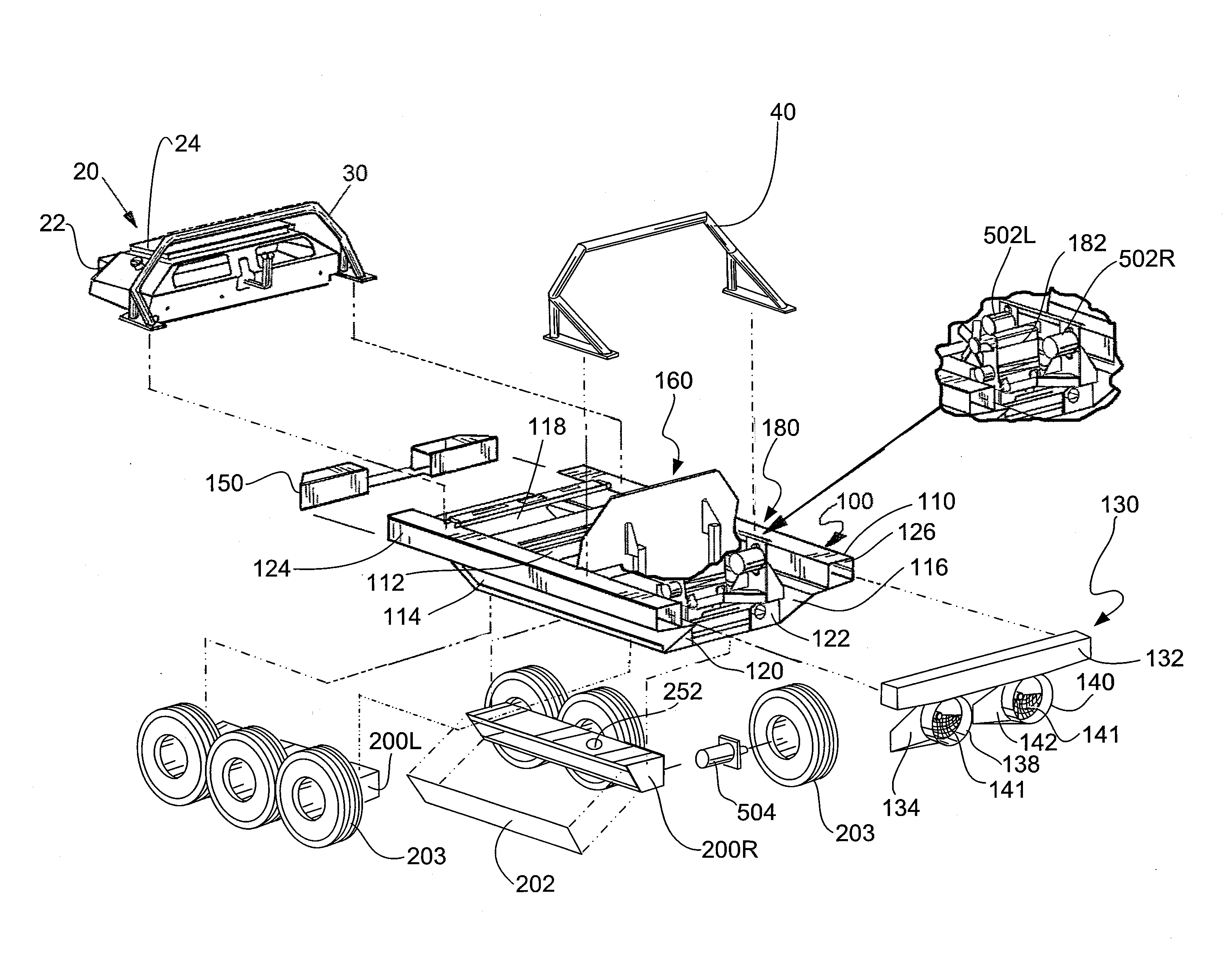
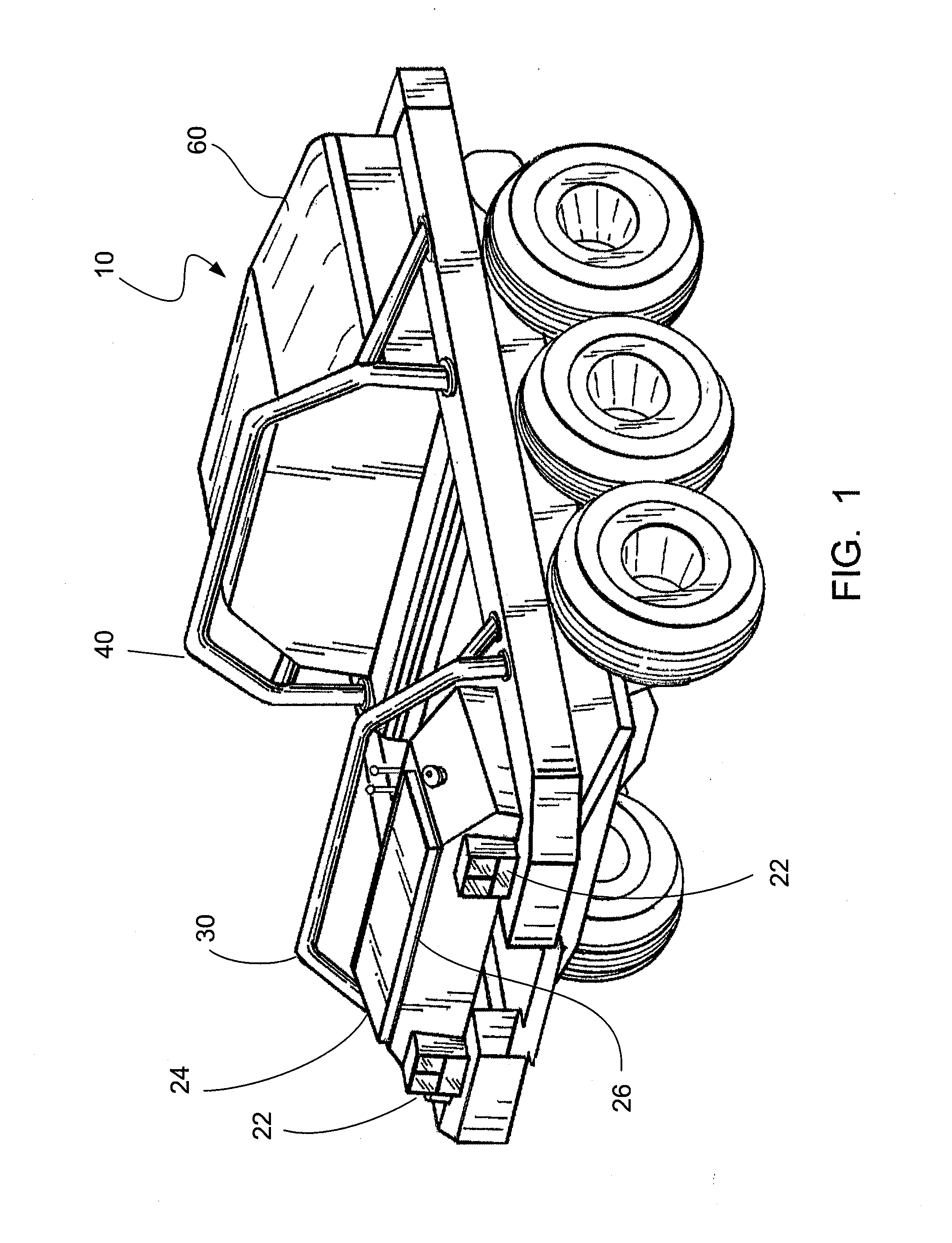
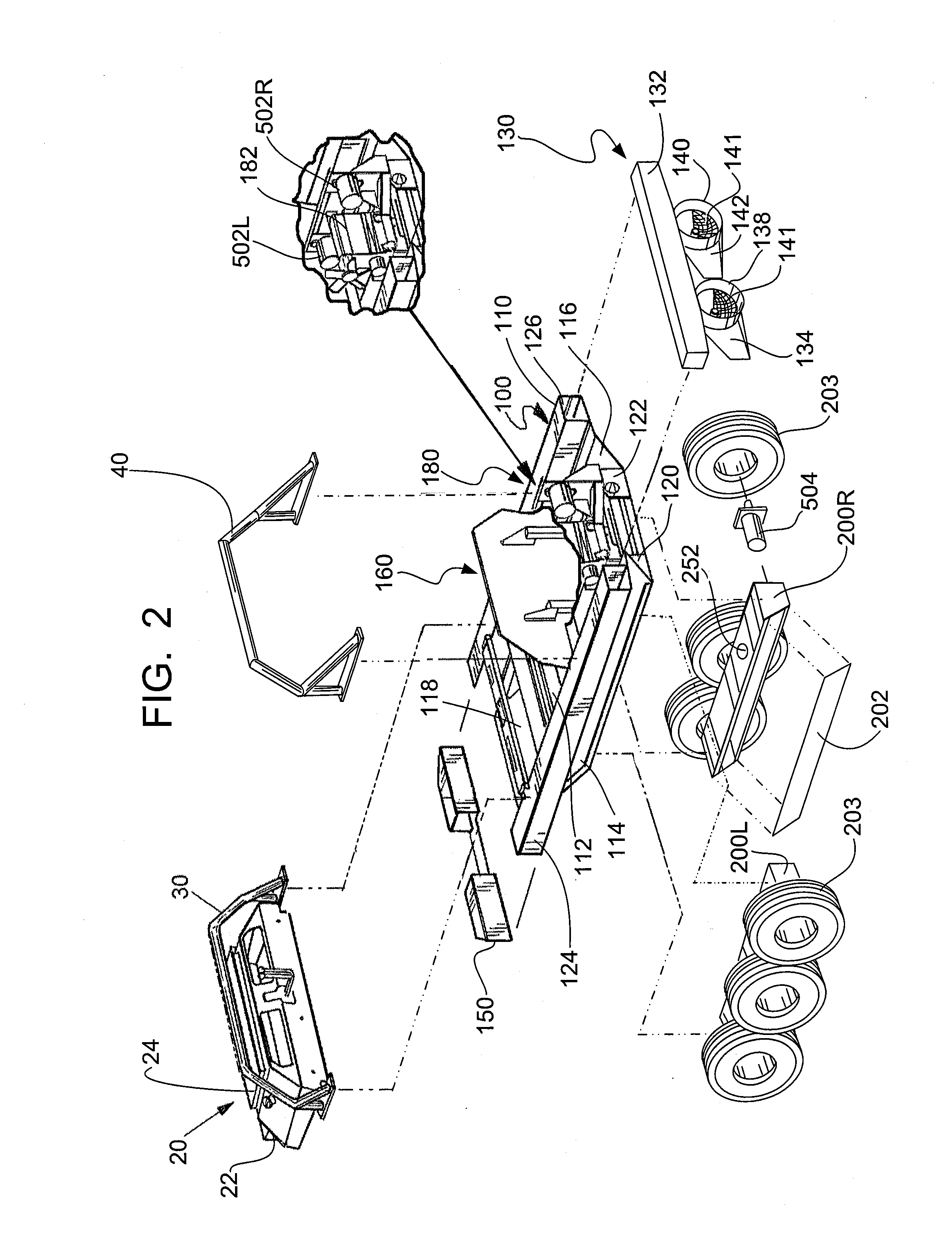
[0041]FIG. 1 illustrates an embodiment of the amphibious all-terrain vehicle 10 according to the present invention. Referring now to FIG. 2, vehicle 10 includes body assembly 100, left undercarriage assembly 2001, right undercarriage assembly 200r, front hood assembly 20, grab bar 30, roll bar 40, and rear hood 60 (shown in FIG. 1).

Body Assembly

[0042]Still referring to FIG. 2, body assembly 100 includes body 110, rear bumper assembly 130, front bumper 150, passenger compartment 160, and mechanical compartment 180. Body 110 includes floor 112, left sidewall 114, right sidewall 116, frontwall 118,left propeller motor mounting flange 120, and right propeller motor mounting flange 122.

[0043]Left propeller motor mounting flange 120 extends upward from the left side of the end of floor 112. The left edge of left propeller mounting flange 120 is permanently attached to the inside surface of left side wall 116, preferably by welding. Right propeller motor mounting flange 122 extends upward...


PUM


Abstract

An amphibious, all-terrain vehicle utilizing a pair of hydrostatic pumps to independently provide power to hydraulic drive mechanisms of the left and right side of the vehicle respectively. The hydraulic drive mechanisms on a side of the vehicle comprise a plurality of hydraulic wheel motors and a hydraulic propeller motor. Using a novel hydraulic manifold assembly, the vehicle can operate in three distinct modes: wheels only, wheels and propellers, and propellers only. The hydraulic manifold assembly also allow the vehicle to by put in neutral mode for starting. The wheel motors are mounted in a pair of undercarriage assemblies that are outside of the vehicle's body and fluidly connected to the hydraulic manifold assembly thorough a hose chase that extends well above the vehicle's waterline to eliminate the potential for water to enter the body of the vehicle when operated in the water.

Description

CROSS-REFERENCE TO RELATED APPLICATIONS[0001]This application claims the benefit of U.S. Provisional Application No. 60 / 812,530, filed Jun. 9, 2006.STATEMENT REGARDING FEDERALLY SPONSORED RESEARCH OR DEVELOPMENT[0002]Not applicableREFERENCE TO MICROFICHE APPENDIX[0003]Not applicableBACKGROUND OF THE INVENTION[0004]1. Field of the Invention[0005]The present invention generally relates to amphibious motor vehicles. More specifically, the invention is an amphibious vehicle that utilizes four, six, or eight independent, hydraulically driven wheels when the wheels are in contact with the ground and a pair of propellers when the vehicle is in water. Further, a single pair of levers controls the speed and direction of the vehicle both on land and in water.[0006]2. Description of the Related Art[0007]A variety of amphibious all-terrain vehicles have been devised in an attempt to allow the user to easily traverse from land to water operation and vice versa quickly and easily. The following p...

Claims


Application Information

Patent Timeline
IPC IPC(8): B60F3/00
CPCB60F3/0007
Inventor GAITHER, R. LOUIS
Owner HYDRATREK IP
Why Eureka
Eureka Blog
Learn More