Helical arm tie down

a technology of helical arm and tie-down, which is applied in the field of medical devices, can solve the problems of difficult radiographic visualization and achieve the effect of improving the accuracy of the position of the open end

Active Publication Date: 2008-09-18
COOK MEDICAL TECH LLC
View PDF4 Cites 14 Cited by
  • Summary
  • Abstract
  • Description
  • Claims
  • Application Information

AI Technical Summary

Benefits of technology

[0010]In one form the invention is said to reside in a stent graft comprising a tubular body of a biocompatible graft material and a side arm extending therefrom, the side arm extending from an ostium in the tubular body and at least partially along the tubular body to an open end of the s

Problems solved by technology

This can make the correct radiographic visualization of the positio

Method used


Image

  • Helical arm tie down
  • Helical arm tie down

Examples


Embodiment Construction

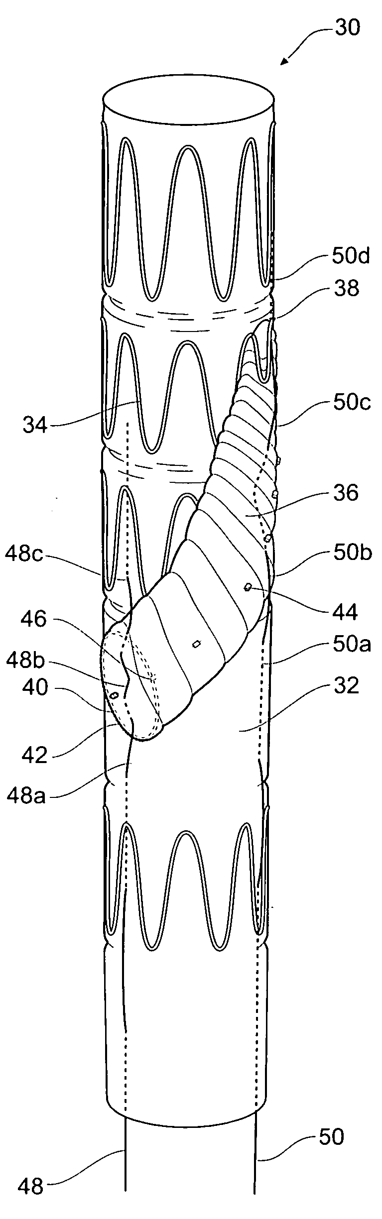
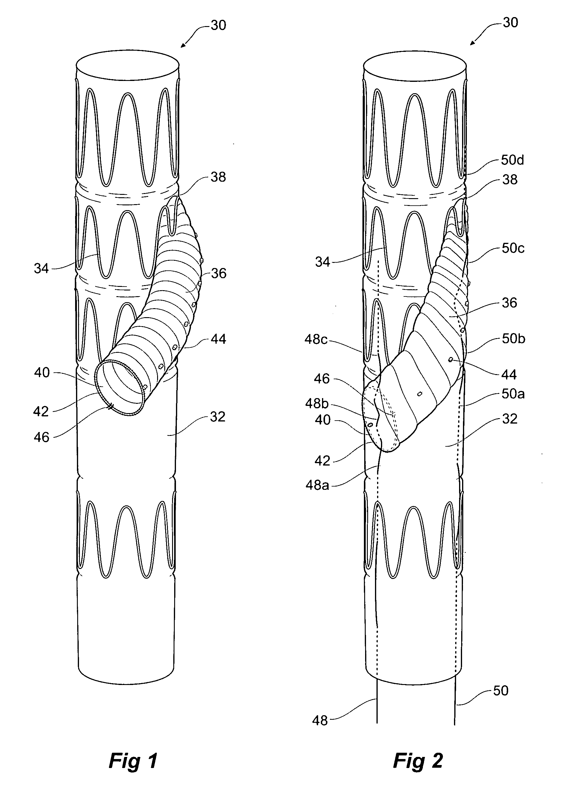
[0028]Looking at FIGS. 1 and 2 there is shown an embodiment of the invention.

[0029]In FIGS. 1 and 2 a stent graft 30 is formed from a tubular body 32 of a biocompatible graft material and has a plurality of zig-zag self expanding stents 34. A tubular side arm 36 extends from an ostium or fenestration 38 in the tubular body 32 in a part helical configuration along and around the tubular body 32 to an open end 40. The open end 20 is directed at an angle of approximately 45° to the longitudinal direction of the tubular body 32 and is reinforced by a resilient ring 42 stitched to the open end 40. The side arm 36 has a line of radiopaque markers 44 along its length. The tubular side arm 36 is formed from a corrugated biocompatible graft material tube and does not have any stents along its length. The resilient ring 42 is stitched to the tubular body 32 by stitching 46 to hold the open end in a desired position.

[0030]If the stent graft 30 was to be constricted and be forced into a sheath ...


PUM


Abstract

An arrangement for temporarily retaining a side arm ( 36 ) of a stent graft ( 30 ) in a selected position during loading thereof onto a deployment device, the side arm extending from an ostium ( 38 ) in the tubular body ( 32 ) and substantially helically around and along the tubular body to an open end ( 40 ). A first tie down wire ( 48 ) is stitched through the tubular body and through the side arm and then through the biocompatible graft material of the tubular body at the open end of the side arm. The stent graft can then be loaded into a sheath of a deployment device for the stent graft. There can be a second tie down wire ( 50 ) stitched through the biocompatible graft material of the tubular body and through the side arm and then through the biocompatible graft material of the tubular body at the ostium end of the side arm. The first and/or second tie down wires can be withdrawn after the stent graft is loaded into the sheath or left in place until delivery.

Description

CROSS-REFERENCE TO RELATED APPLICATIONS[0001]This application claims priority of provisional application Ser. No. 60 / 906,477, filed Mar. 12, 2007.TECHNICAL FIELD[0002]This invention relates to a medical device and more particularly to an arrangement for assembly of a medical device onto an introduction device.BACKGROUND OF THE INVENTION[0003]This invention will be particularly discussed in relation to stent grafts for placement into the thoracoabdominal aorta for the treatment of aneurysms and more specifically in relation to juxtarenal placement. The invention, however, is not so restricted and may be applied to stent grafts for placement in any lumen of the human or animal body.[0004]There has been devised a thoracoabdominal stent-graft with one or more side arms for the celiac, superior mesenteric and / or renal arteries. One particular form of stent graft includes a side arm which is a graft material tube which extends at least partially helically around the stent graft from a fen...

Claims


Application Information

Patent Timeline
IPC IPC(8): A61F2/06A61F2/82
CPCA61F2/07A61F2/95A61F2/954A61F2002/061A61F2220/0075A61F2002/821A61F2250/0098A61F2/89A61F2002/065A61F2/856A61F2/844A61F2002/9511A61F2220/0025A61F2230/0069
Inventor HANNAY, GWYNNE
Owner COOK MEDICAL TECH LLC
Why Eureka
Try Eureka