Handle

a technology for handles and handles, applied in the field of handles, can solve the problems of not being secured against being pulled off, the handle element and the handle core will become separated, and achieve the effect of reducing the transmission of vibrations

Inactive Publication Date: 2008-06-26
ROBERT BOSCH GMBH
View PDF17 Cites 15 Cited by
  • Summary
  • Abstract
  • Description
  • Claims
  • Application Information

AI Technical Summary

Benefits of technology

[0007]The present invention is directed to a handle with a handle shell and a handle core. At one end, the handle core is equipped with a fastening element for attaching the handle to the hand-held power tool, the handle core extending to the end of the handle sleeve opposite to the fastening element. An intermediate space is located between the handle sleeve and the handle core. The handle sleeve and handle core therefore do not contact each other. The handle sleeve is essentially designed, e.g., as a hollow cylinder. The handle core is essentially shaped, e.g., as a cylinder, and is coaxial with the handle sleeve. At least one dampening element is provided in the intermediate space between the handle sleeve and the handle core. The dampening element reduces the transmission of vibrations from the handle core to the handle sleeve and, therefore, to the operator of the hand-held power tool.
[0008]To safeguard the handle from being pulled off, the handle core and the handle sleeve are designed such that the handle core has a contactless overhanging section in the handle sleeve. The overhanging section is designed to be contactless, since the handle core and the handle sleeve do not touch each other, but rather are connected with each other only via dampening elements. The handle core comes in contact with the handle sleeve only when the dampening element fails. The overhanging section prevents the handle core and handle sleeve from becoming separated. The contactless overhanging section therefore ensures axial retention if the dampening element should fail.

Problems solved by technology

The handle made known in DE 103 48 973 A1 has the disadvantage that it is not secured against being pulled off.
If the resilient material of the spacer tears, e.g., due to material fatigue, there is a risk that the handle element and the handle core will become separated.

Method used


Image

  • Handle
  • Handle
  • Handle

Examples


first embodiment

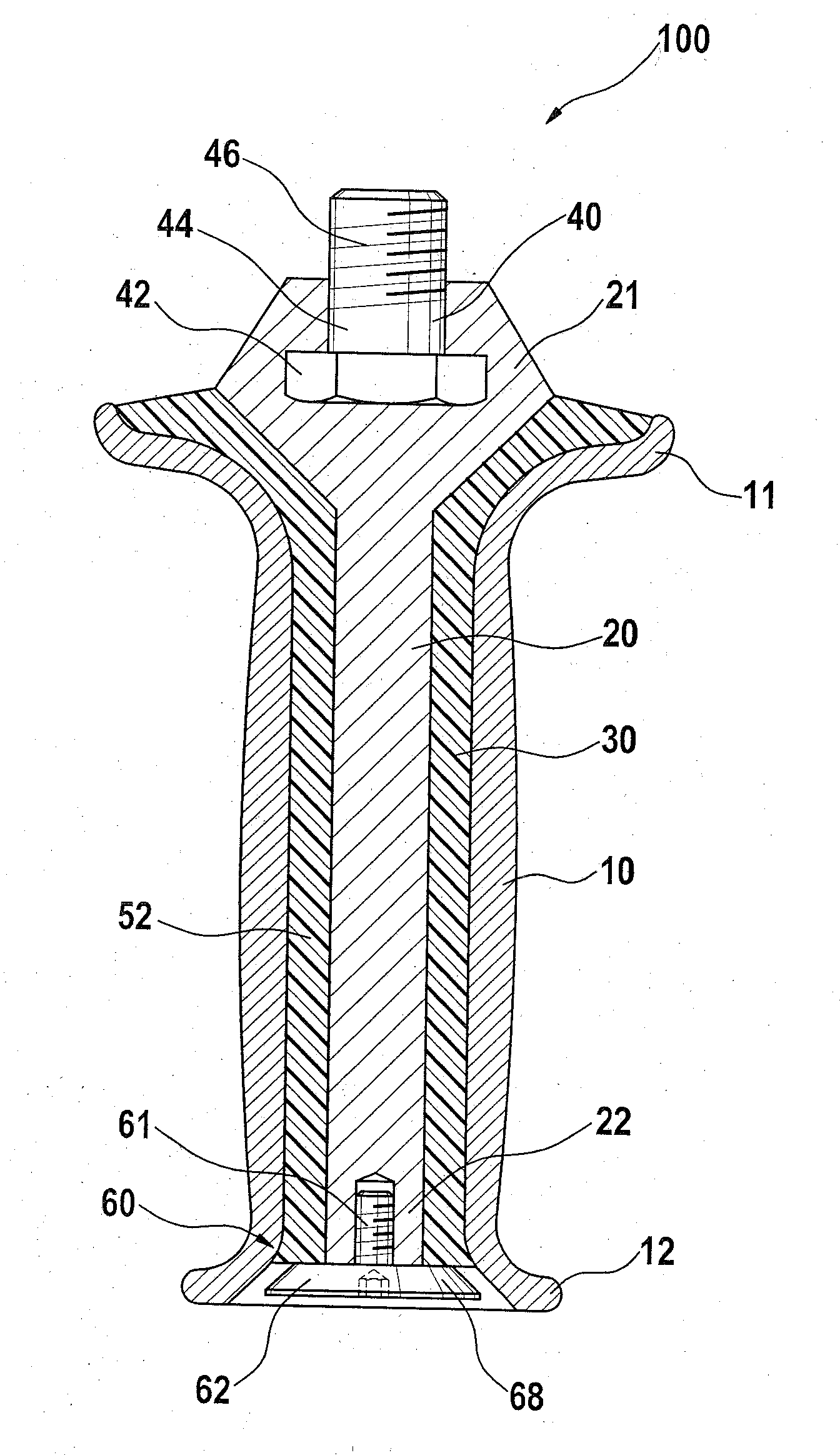
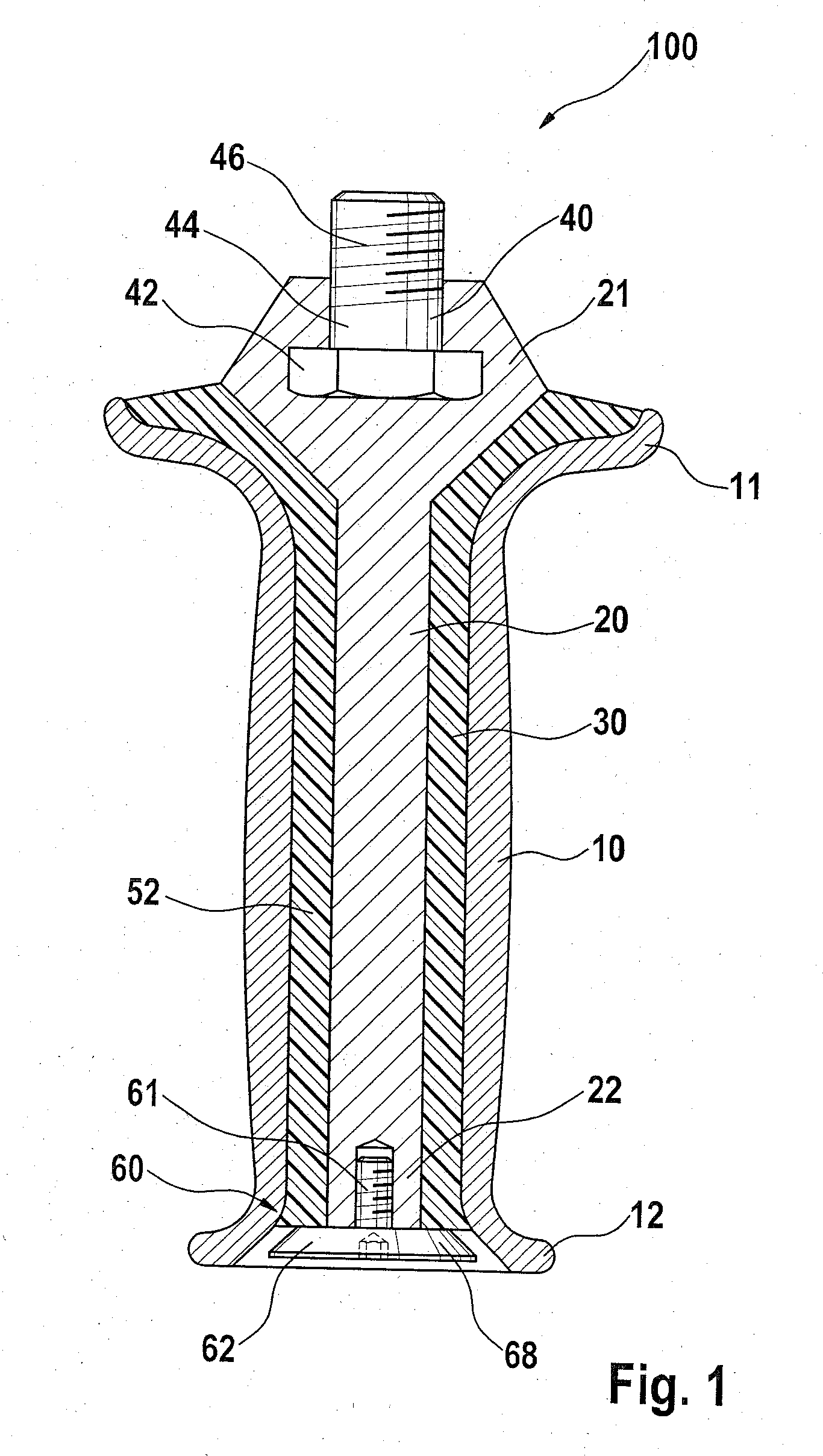
[0031]FIG. 1 shows an inventive handle 100, which may be used as an additional handle for a mains-operated or cordless hand-held power tool (not shown). Handle 100 includes a handle sleeve 10, which is designed essentially as a hollow cylinder. A handle core 20 is coaxial with and distanced from handle sleeve 10. Handle core 20 is designed essentially as a cylinder. Handle core 20 accommodates a fastening element 40 on its upper end shown in FIG. 1. In the embodiment shown, fastening element 40 is a screw, screw head 42 of which is accommodated in handle core 20, and screw neck 44—with screw thread 46—of which extends at least partially out of handle core 20 and handle sleeve 10.

[0032]Fastening element 40 serves to detachably attach handle 100 to a not-shown hand-held power tool. Handle core 20 extends essentially from one end 11 of handle sleeve 10 to the other end 12. Handle core 20 may also extend out of handle sleeve 10 at its end 21 facing fastening element 40, as shown in FIGS...

second embodiment

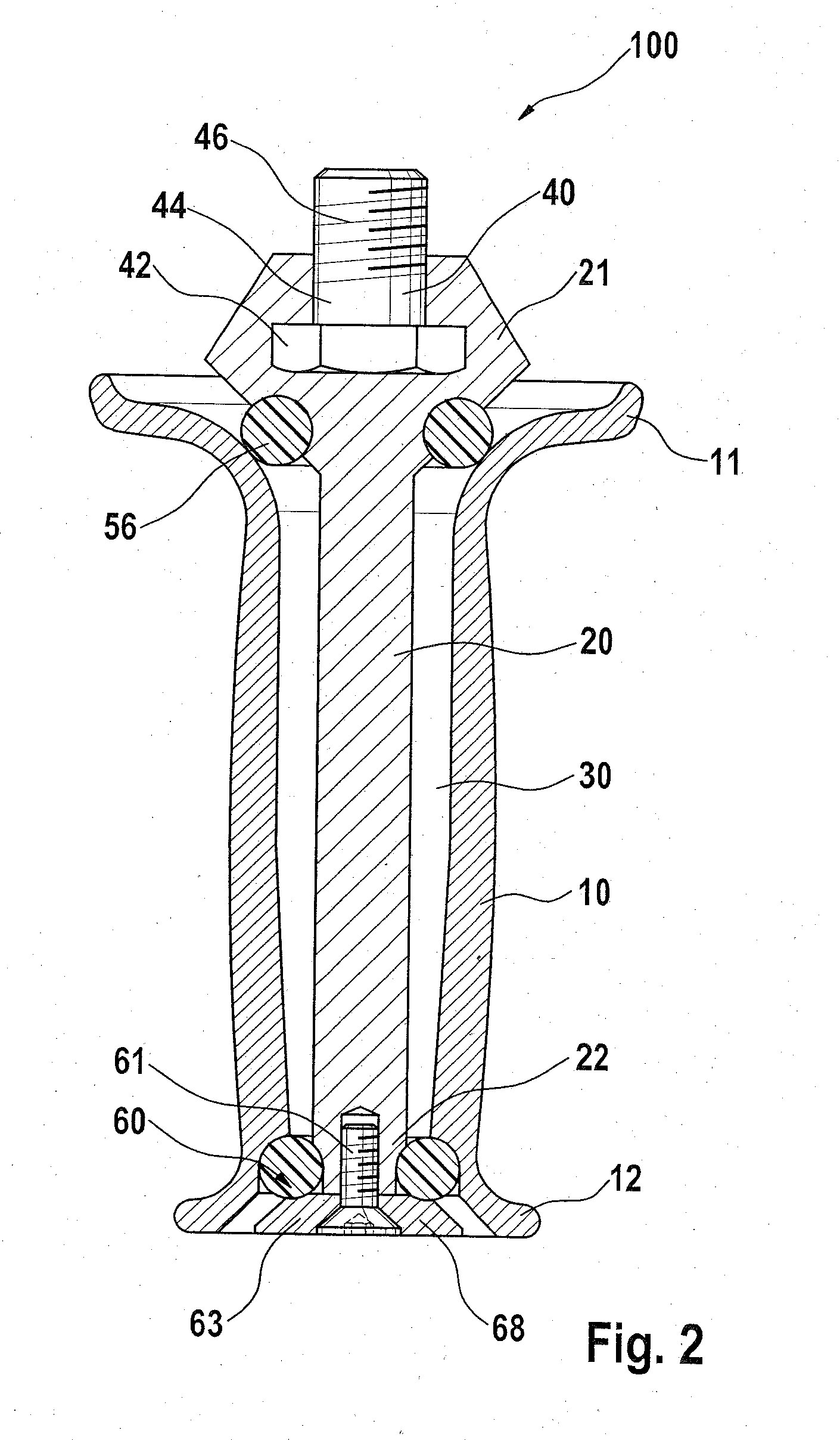
[0038]In a second embodiment, as shown in FIG. 2, the base is formed by a disk 63, which is installed, as a separate piece, on the end face of handle core 20 using a screw 61. Similar to screw head 62 shown in FIG. 1, disk 63 extends beyond handle core 20 in the radial direction. In a further embodiment, as shown in FIG. 3, the base is integrally formed directly on handle core 20, in the form of a collar 64.

[0039]In the embodiment shown in FIG. 4, handle core 20 is designed as a single piece with fastening element 40. A screw 25 is installed in handle sleeve 10 such that it performs the function of handle core 20 and fastening element 40. Screw neck 26 is coaxial with handle sleeve 20 and serves as handle core 20. Screw thread 27 extends at least partially out of handle sleeve 20 and serves as fastening element 40. Screw head 28 is located on opposite end 12 of handle sleeve 10, and performs the function of overhanging element 68.

[0040]In the embodiment shown in FIG. 3, in contrast ...


PUM


Abstract

A handle includes a handle sleeve and a handle core, the handle core includes a fastening element on one end and extends to the end of the handle sleeve opposite to the fastening element, an intermediate space is located between the handle sleeve and the handle core, and at least one dampening element is provided in the intermediate space, and the handle core includes a contactless overhanging section in the handle sleeve.

Description

CROSS-REFERENCE TO A RELATED APPLICATION[0001]The invention described and claimed hereinbelow is also described in German Patent Application DE 102006061247.7 filed on Dec. 22, 2006. This German Patent Application, whose subject matter is incorporated here by reference, provides the basis for a claim of priority of invention under 35 U.S.C. 119(a)-(d).BACKGROUND OF THE INVENTION[0002]The present invention relates to a handle, in particular for a hand-held power tool.[0003]Numerous power tools, such as angle grinders, drills, and rotary hammers, are equipped with an extra handle. To prevent vibrations that occur during operation of the power tool from being transmitted to the operator via the additional handle, additional handles are often provided with vibration-dampening means.[0004]Publication DE 103 48 973 Al makes known a vibration-dampened handle that includes a sleeve-shaped outer handle element and a sleeve-shaped or cylindrical inner handle core. The inner handle core is des...

Claims


Application Information

Patent Timeline
Patent Type & Authority Applications(United States)
IPC IPC(8): B25F5/02
CPCB25F5/006Y10T16/48B25F5/026B23B27/002B24B23/00B25D17/04B25F5/02
Inventor WIKER, JUERGENEICHER, BERNHARDSCHADOW, JOACHIMHEESS, STEFANFRANK, MARIOKEUSCH, SIEGFRIEDMUELLER-BOYSEN, ULRICHMAUTE, JOERGESENWEIN, FLORIANSCHULLER, MARCUSEICHER, ROSWITHA
Owner ROBERT BOSCH GMBH
Why Eureka
Try Eureka