Liquid sealed vibration isolating device

US20080230968A1Active Publication Date: 2008-09-25HONDA MOTOR CO LTD +1

Image

  • Liquid sealed vibration isolating device
  • Liquid sealed vibration isolating device
  • Liquid sealed vibration isolating device

Examples


Embodiment Construction

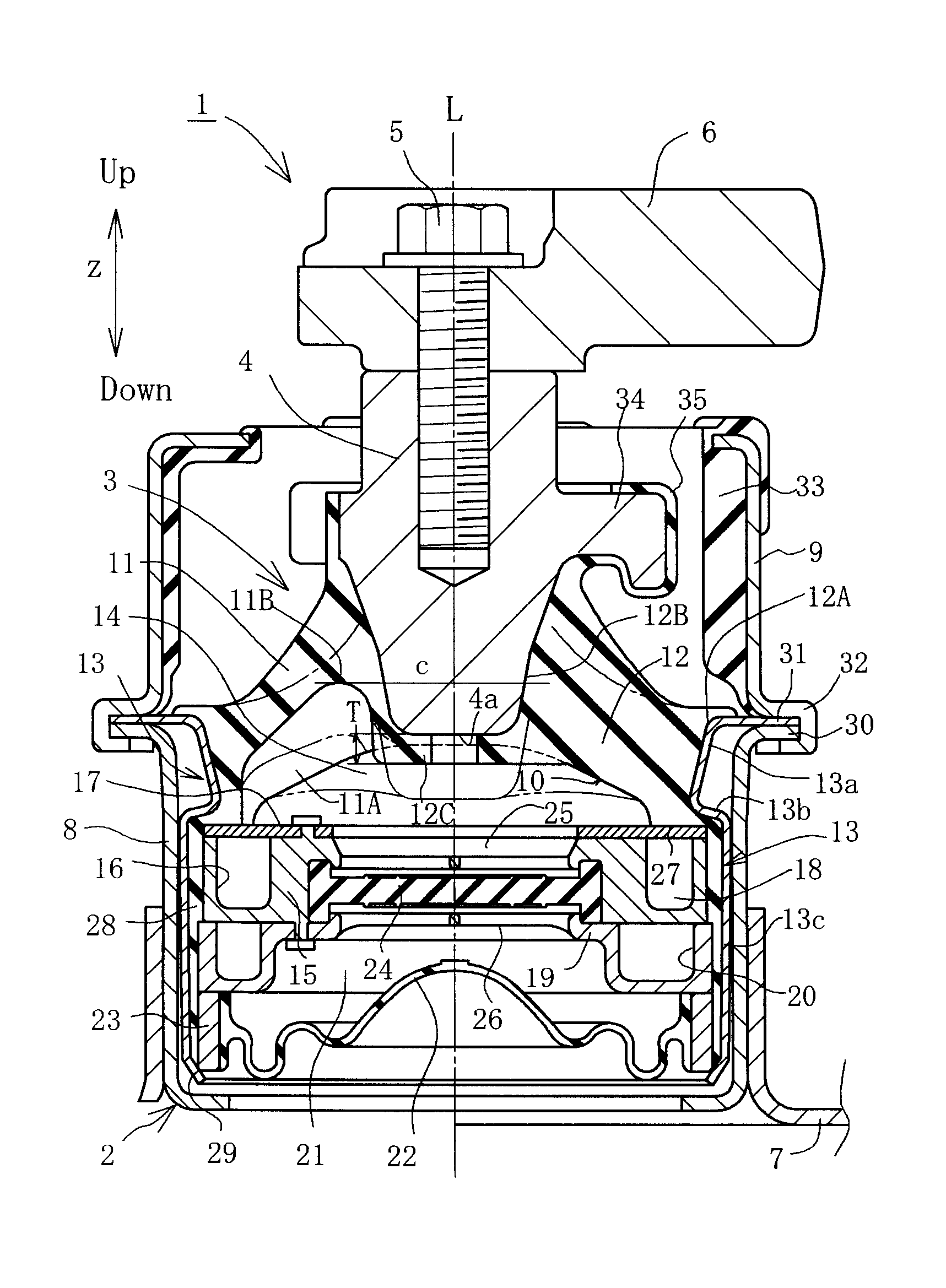
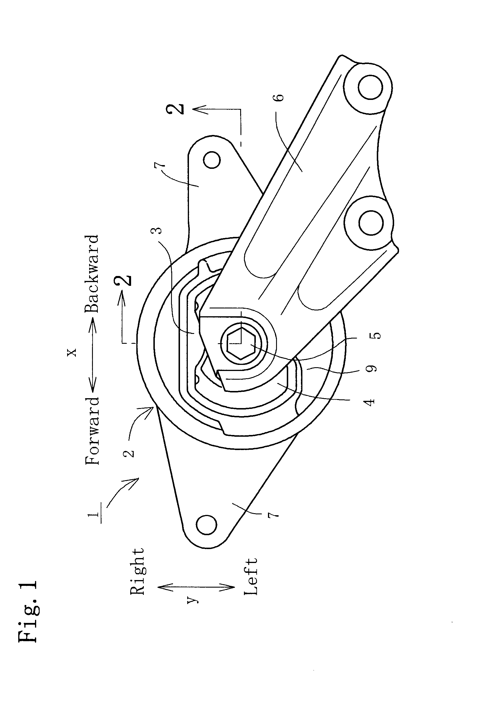
[0031]Hereinafter, an embodiment embodied in an engine mount for motor vehicles will be explained with reference to the accompanying drawings, wherein FIG. 1 is a plan view of an engine mount 1. An insulator 3 is integrally provided on an upper part of a circular main body 2. A vibration input portion 4 of a block-shaped metallic member is implanted in the central area of the insulator 3 so as to be united therewith. On the tip of the vibration input portion 4 there is mounted one end of an engine bracket 6 through a bolt 5. The vibration input portion 4 is made of a rigid body such as proper metal or the like. The other end of the engine bracket 6 is mounted on an engine (not shown). The reference character 7 denotes a metallic fitting integrally welded with a lower portion of the main body 2, which is bolted to a vehicle body.

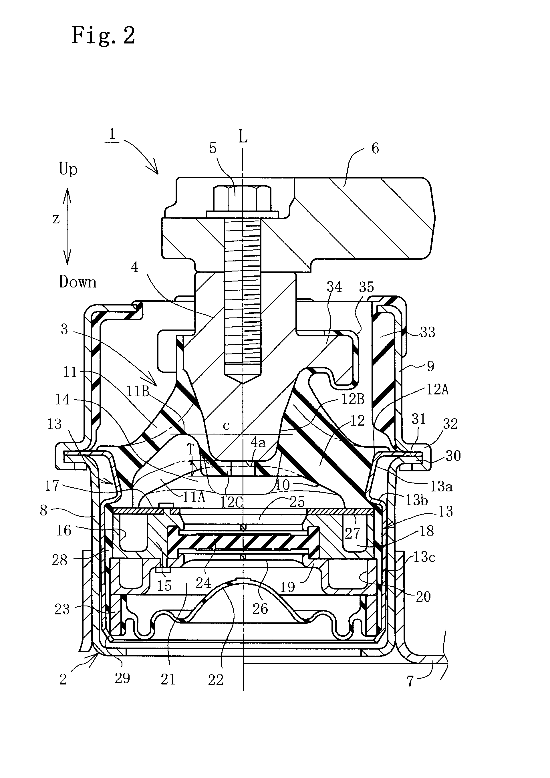
[0032]FIG. 2 is a cross sectional view taken on line 2-2 of FIG. 1 and is sectioned along a center line L passing central axes of the vibration input portion...


PUM

PropertyMeasurementUnit
Lengthaaaaaaaaaa
Thicknessaaaaaaaaaa
Thicknessaaaaaaaaaa

Abstract

A vibration isolating device includes an insulator for isolating the transmission of an inputted vibration by an elastic deformation. A principal vibration input portion is provided in a central area of a concave curved wall portion formed in the insulator. A thin wall portion and a thick wall portion are formed by relatively varying a thickness of the insulator around the vibration input portion, wherein the concave curved wall portion of the insulator is formed in a substantially circular shape when viewed in a principal vibration inputted direction. The thick wall portion is formed substantially in the shape of a belt of a predetermined width and extends across the concave curved wall portion in the diametrical direction thereof while passing the vibration input portion. A rigid body covering portion for covering a surface of a metallic member of the vibration input portion is provided in the central area of the thick wall portion. A thickness of the rigid body covering portion is at least 1.7 mm.

Description

BACKGROUND OF THE INVENTION[0001]1. Field of the Invention[0002]The present invention relates to a vibration isolating device for use in an engine mount or the like for motor vehicles and particularly, to the device of which durability is improved in the case of employing an insulator provided with a thin wall portion.[0003]2. Description of the Related Art[0004]As a vibration isolating device for use in an engine mount or the like for the motor vehicles, there is known a liquid sealed vibration isolating device provided with a generally dome-shaped insulator which forms a portion of a liquid chamber, wherein a principal vibration is inputted from a vibration inputting section provided around a center portion of the insulator. Also, there is proposed that the thickness of the insulator is relatively varied to provide a thick wall portion and a thin wall portion, and the whole of the insulator is formed to be low spring constant by the thin wall portion so as to control an increase i...

Claims


Application Information

Patent Timeline
25 Sep 2008
Publication
US20080230968A1
IPC
F16F9/05
CPC
F16F13/101
Inventors
KUBO, NOBUO; YANAGASE, HIROSHI