
Apparatus and Method For Reference Level Based Write Strategy Optimization

Inactive Publication Date: 2008-09-25
KONINKLIJKE PHILIPS ELECTRONICS NV
View PDF3 Cites 5 Cited by
  • Summary
  • Abstract
  • Description
  • Claims
  • Application Information

AI Technical Summary

Benefits of technology

[0019]The present invention renders it possible to optimize a recording process on storage media having data capacities above 30 GB, such as, for example, in the range of 30-37 GB, since the reference levels may be provided for such data densities. This is an advantage since currently no alternative method exists for optimizing the recording process on such high-capacity media.
[0020]An embodiment of the apparatus according to the invention is defined in dependent claim 2. This embodiment has the advantage that by determining the asymmetry of an optical effect from the reference levels as a function of the length of the optical effect, it is rendered possible to extract run-length dependent asymmetry information from the reference levels, thereby enabling a run-length dependent optimization of the write strategy.
[0021]The asymmetry of a waveform is a direct measure of how long the marks are relative to the spaces, and by optimizing the write strategy based on the asymmetry correctly sized optical effects are ensured.
[0023]An embodiment of the apparatus according to the invention is defined in dependent claim 6. This embodiment has the advantage that by reading a first part of the sequence of optical effects during a first part of the recording process, optimizing the write strategy in an optimization process, and subsequently using the optimized write strategy in a second part of the recording process, an optimal write quality is ensured for the entire recording process.

Problems solved by technology

Use of such a limited amount of information renders it problematic to fulfill the precise power control requirements as needed, for example, in high-speed BD recordings.

Method used


Image

  • Apparatus and Method For Reference Level Based Write Strategy Optimization
  • Apparatus and Method For Reference Level Based Write Strategy Optimization
  • Apparatus and Method For Reference Level Based Write Strategy Optimization

Examples


Embodiment Construction

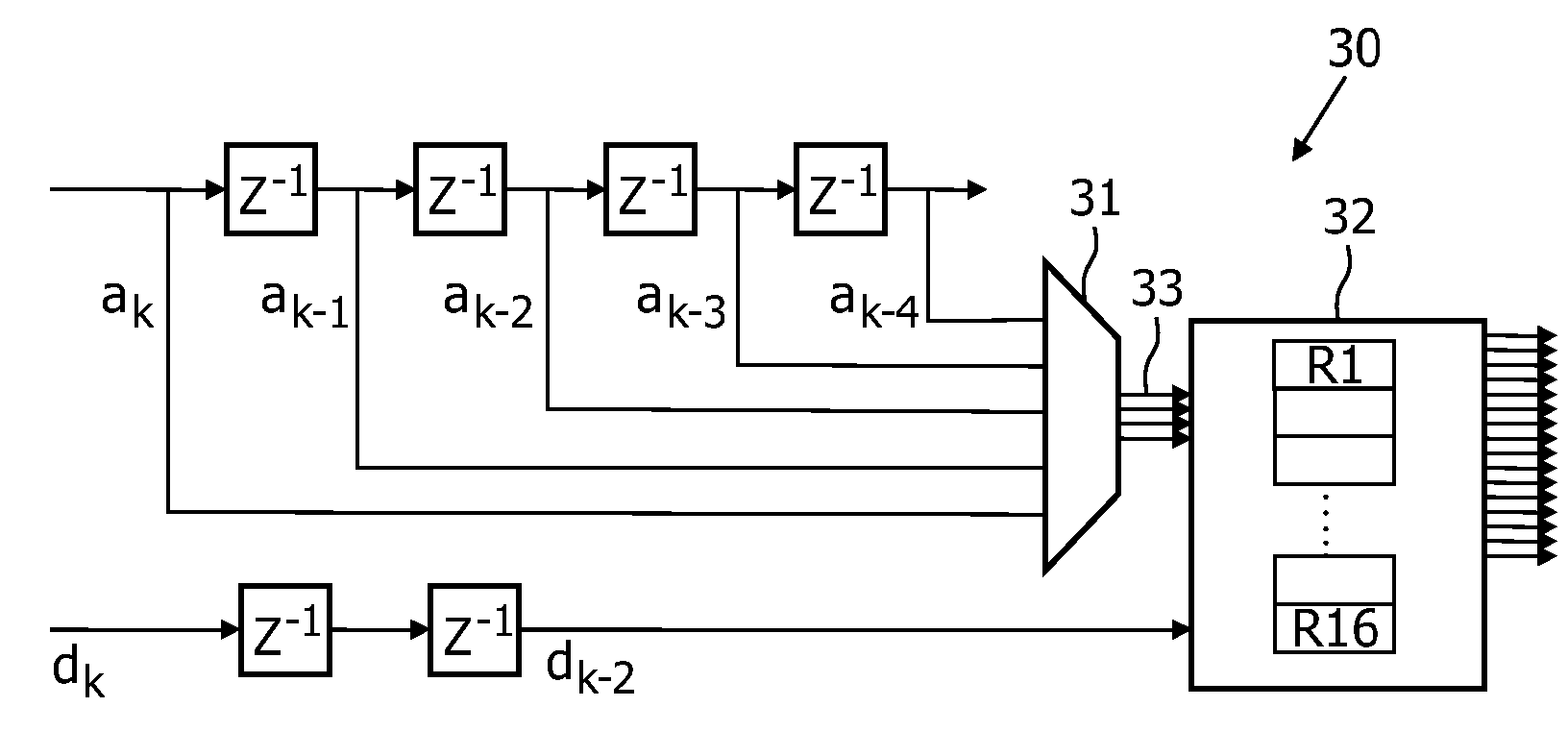
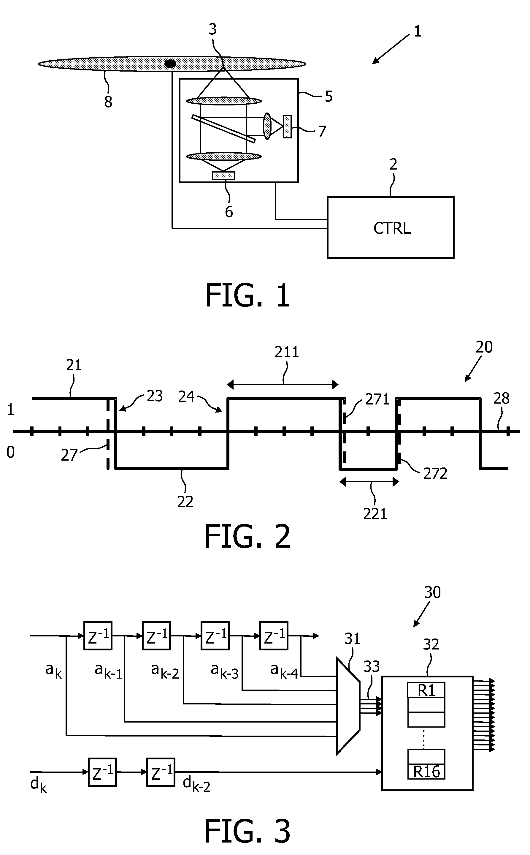
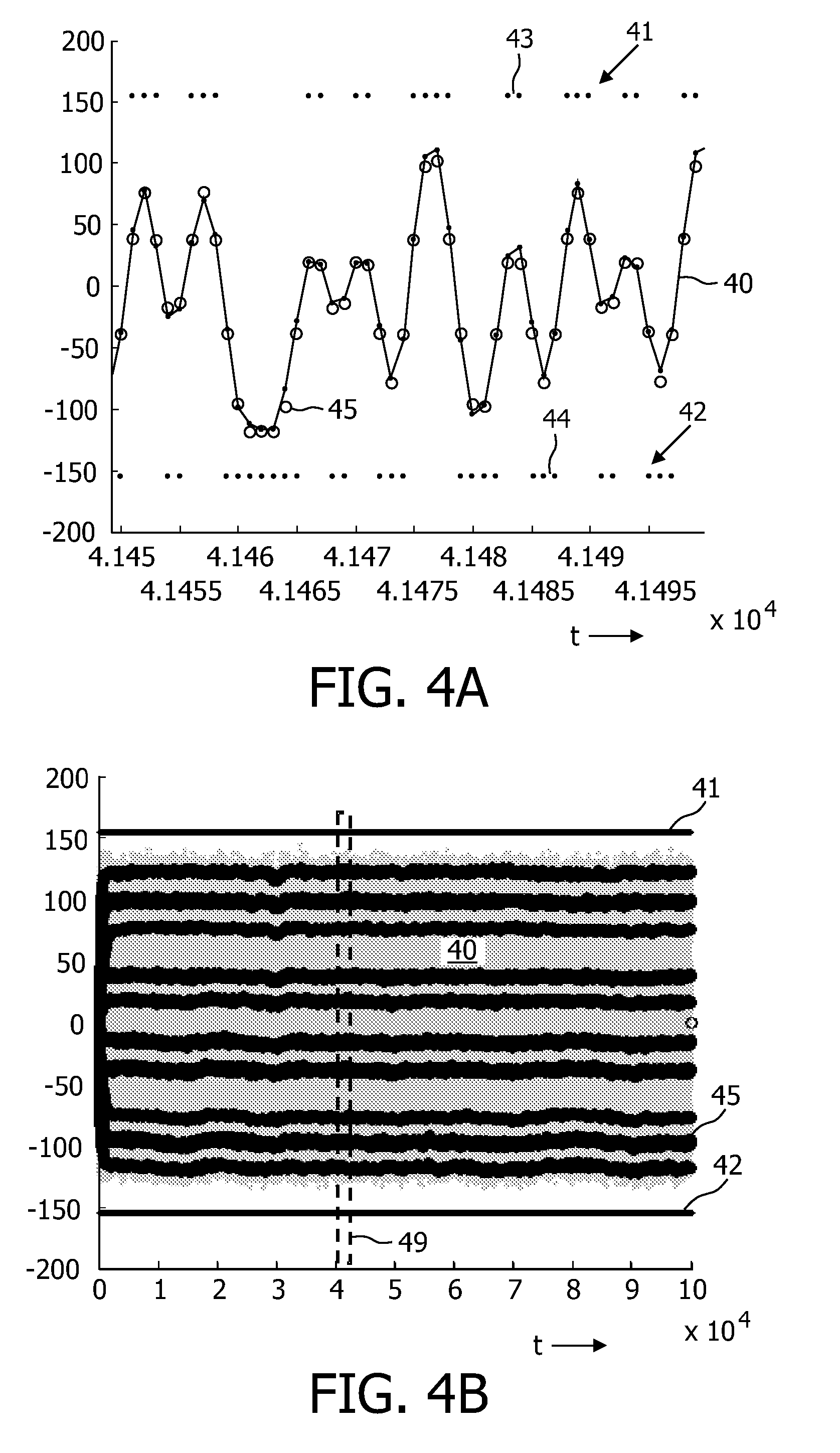
[0038]FIG. 1 schematically illustrates the elements of an optical recording apparatus 1 according to the present invention capable of reading and / or writing information from and / or to an optical record carrier 8. It is noted that an optical recording apparatus comprises a large number of elements with various functions, only the most relevant of which are illustrated here. Control means CTRL 2 refers to any type of control means used for controlling the optical recording apparatus. This control means CTRL 2 may include such control elements as mechanical control elements, electronic control elements, and microprocessor means. Mechanical control elements include motor means for rotating the disc shaped optical record carrier 8 and for moving the optical pickup unit 5. Electronic control elements include control elements for controlling the motion of the optical pickup unit 5. The microprocessor means (e.g., integrated circuit (IC) means) may include hardwired processing means and / or ...


PUM


Abstract

The invention relates to an optical recording apparatus comprising means for optimizing a write strategy in a recording process. The apparatus comprising a radiation source for emitting a radiation beam in accordance with the write strategy, a read unit so as to provide a read signal, a bit detector for providing modulation bits corresponding to the read signal, a processing unit for grouping the modulation bits into modulation bit sequences and for correlating each modulation bit sequence of the read signal to a reference level, the reference level corresponding to the average amplitude of the read signal for a given modulation bit sequence. Average transition shifts of leading and / or trailing edges are determined based on the position of the reference levels, and at least one of the one or more write parameters in the write strategy is optimized in an optimization process based on the relative values of the reference levels. Optionally, the asymmetry of an optical effect may be determined from the reference levels so that the write strategy is optimized based on the asymmetry.

Description

FIELD OF THE INVENTION[0001]The invention relates to an optical recording apparatus comprising an optimized write strategy control and to a corresponding method for optimizing a write strategy in an optical recording process. The invention relates in particular to the optimization of one or more parameters of the write strategy.BACKGROUND OF THE INVENTION[0002]The optimal amount of radiation power required to record data on optical media (such as for example CD, DVD, and BD) depends inter alia on the specific medium used, on the recording speed, and may even depend on the location on the medium where the data is to be recorded. It is important that the correct radiation power is supplied to the medium, since incorrect radiation power settings may result in incorrect optical effects (often referred to as marks), such as too small or too large effects. Since these optical effects represent the recorded data, incorrect radiation power settings may consequently result in erroneous recor...

Claims


Application Information

Patent Timeline
IPC IPC(8): G11B7/125
CPCG11B7/00456G11B7/1263G11B7/0045
Inventor VLUTTERS, RUUD
Owner KONINKLIJKE PHILIPS ELECTRONICS NV
Learn More