Device, method and recording medium containing program for separating image component

a technology of image component and recording medium, which is applied in the field of device, method and recording medium containing program for separating image component, can solve the problems of further separation of the component representing the body tissues into the soft parts

Inactive Publication Date: 2008-09-25
FUJIFILM CORP
View PDF5 Cites 27 Cited by
  • Summary
  • Abstract
  • Description
  • Claims
  • Application Information

AI Technical Summary

Benefits of technology

[0041]Further, since each component distributes over the entire subject, most of the pixels of the component image have pixel values other than 0. Therefore, most of the pixels of an image obtained through the above-described image composition are influenced by the component image. For example, if the above-described color conversion is carried out bef

Problems solved by technology

However, the methods described in Japanese Unexamined Patent Publication Nos. 2002-152593 and 2004-064637 carry out only separation between two components using two images.
For example, the method of Japanese Unexamined Patent Publication No. 2004-064637 can separate an ima

Method used


Image

  • Device, method and recording medium containing program for separating image component
  • Device, method and recording medium containing program for separating image component
  • Device, method and recording medium containing program for separating image component

Examples


second embodiment

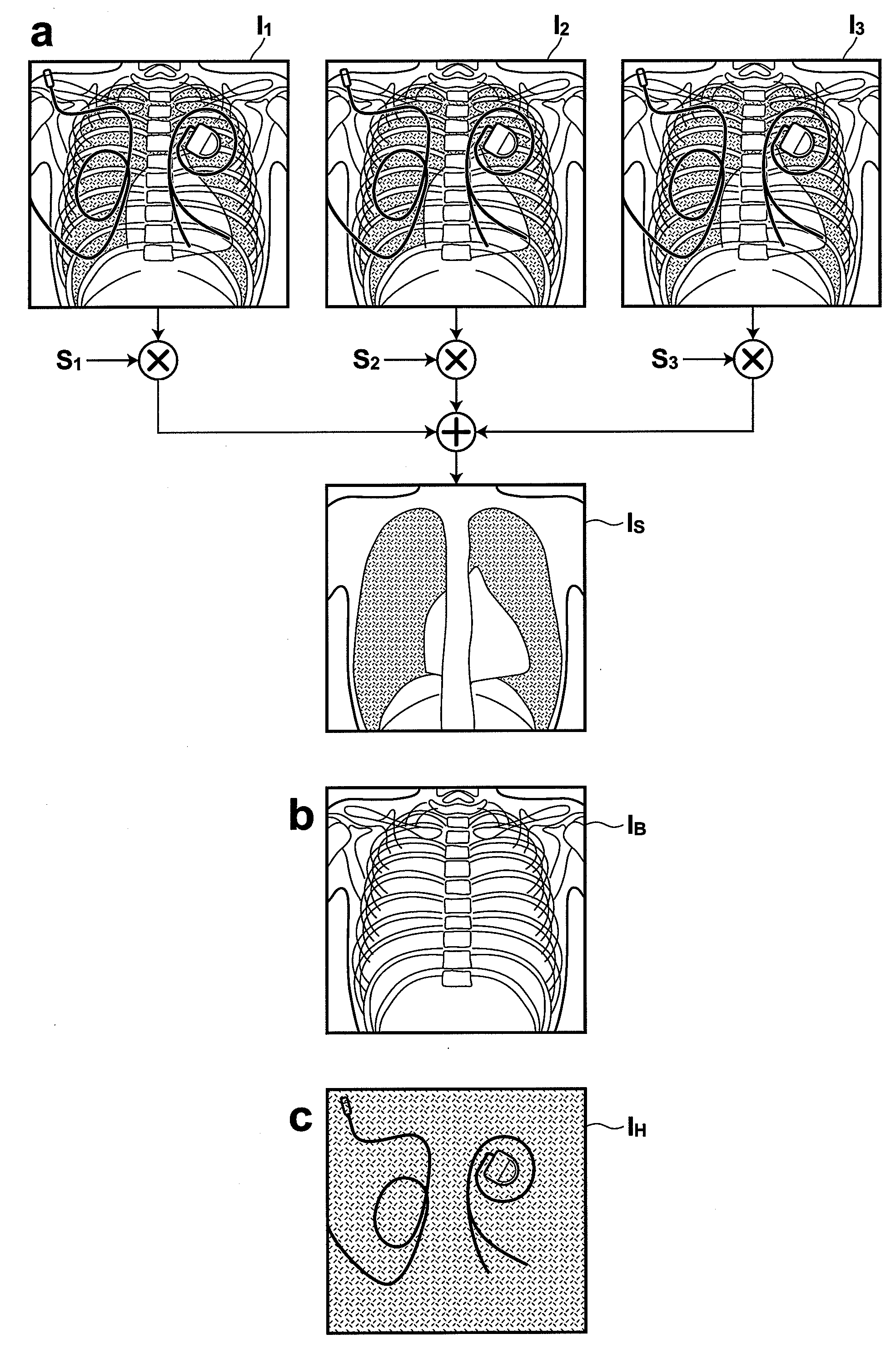
[0088]Therefore, in the invention, a pixel value of each pixel of one of the inputted three radiographic images are used as a parameter, and the above-described weighting factors are determined for each pixel based on this parameter. Specifically, assuming that a pixel value of a pixel p in each inputted image In of each combination of the corresponding pixels is In (p) and the image containing the parameter pixels is I1, weighting factors for the respective components to be separated for each pixel are expressed as sn(I1(p)), bn(I1(p)) and hn(I1(p)), respectively. Using these expressions, a pixel value Is(p), Ib(p) or Ih(p) for each pixel p in each component image is expressed as the following equation (11), (12), (13):

Is(p)=s1(I1(p))·I1(p)+s2(I1(p))·I2(p)+s3(I1(p))·I3(p)   (11),

Ib(p)=b1(I1(p))·b1(p)+b2(I1(p))·I2(p)+b3(I1(p))·I3(p)   (12),

Ih(p)=h1(I1(p))·I1(p)+h2(I1(p))·I2(p)+h3(I1(p))·I3(p)   (13).

[0089]It should be noted that the image of the parameter pixels may be I2 or I3, and...

first embodiment

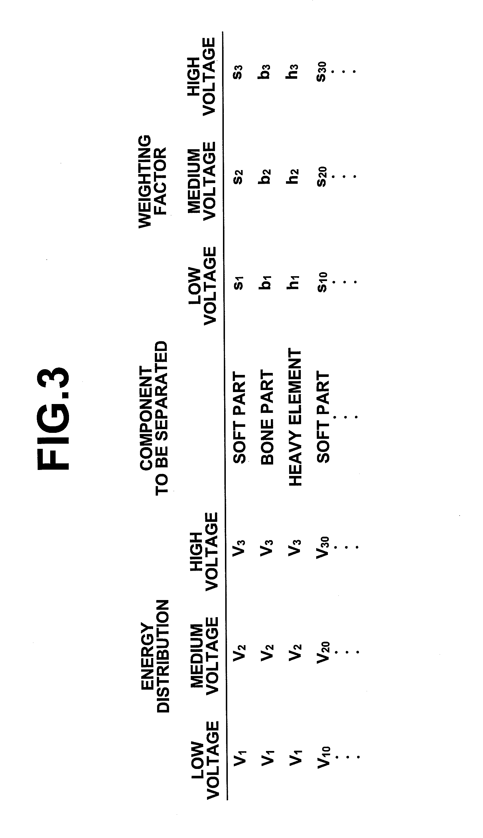
[0090]An example of implementation of these equations is described below. First, as shown in FIG. 6, an item (“pixel value from / to”) indicating ranges of pixel values of the parameter image I1 is added to the weighting factor table 31 in the first embodiment, so that a weighting factor for each pixel of each image can be set for each energy distribution information of the image, for each component to be separated and for each pixel value range of the pixel in the image I1 of the corresponding pixels. In the example shown in FIG. 6, assuming that the energy distribution information, i.e., the tube voltages of the three inputted images are V1, V2 and V3, and the component to be separated is the soft part component, the weighting factors for the respective inputted images are: s11, s12 and s13 if the pixel value of the image I1 is equal to or more than p1 and less than p2; s21, s22 and s23 if the pixel value of the image I1 is equal to or more than p2 and less than p3; and s31, s32 and...

third embodiment

[0093]Next, the invention will be described, in which the weighting factors are indirectly obtained. In this embodiment, a model using attenuation coefficients for the respective components in the above equations (1), (2) and (3) is used. As shown in FIG. 8, the attenuation coefficient monotonically decreases as the energy distribution (tube voltage) of the radiation for each image increases, and increases as the atomic number of the component increases.

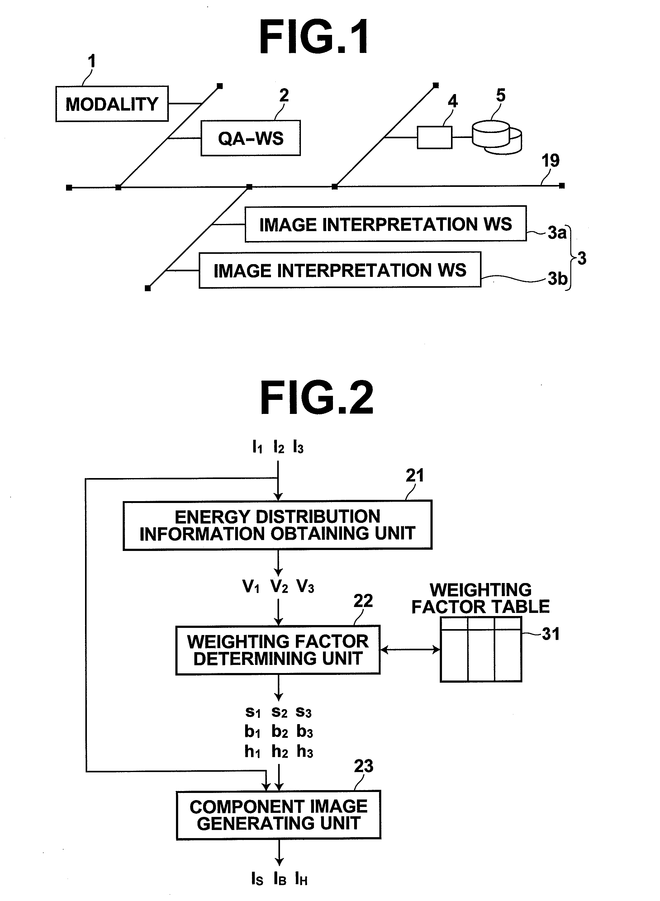
[0094]FIG. 7 is a block diagram schematically illustrating the functional configuration and data flow of the image component separating device of this embodiment. As shown in the drawing, the difference between this embodiment and the first and second embodiments lies in that an attenuation coefficient determining unit 24 is added and the weighting factor table 31 is replaced with an attenuation coefficient table 32.

[0095]The attenuation coefficient determining unit 24 references the attenuation coefficient table 32 with the energy d...


PUM


Abstract

A technique for appropriately separating three components contained in radiographic images is disclosed. A component image generating unit separates an image component, which represents any one of a soft part component, a bone component and a heavy element component including an element having an atomic number higher than that of the bone component in a subject, from inputted three radiographic images, which represents degrees of transmission of three patterns of radiations having different energy distributions through the subject, by calculating a weighted sum for each combination of corresponding pixels between the three radiographic images using predetermined weighting factors.

Description

BACKGROUND OF THE INVENTION[0001]1. Field of the Invention[0002]The present invention relates to a device and a method for separating a specific image component in an image through the use of radiographic images taken with radiations having different energy distributions, and a recording medium containing a program for causing a computer to carry out the method.[0003]2. Description of the Related Art[0004]The energy subtraction technique has been known in the field of medical image processing. In this technique, two radiographic images of the same subject are taken by applying radiations having different energy distributions to the subject, and image signals representing pixels of the two radiographic images are multiplied with suitable weighting factors and subtraction between corresponding pixels of these images is carried out to obtain difference signals, which represents an image of a certain structure. Using this technique, a soft part image from which the bone component has be...

Claims


Application Information

Patent Timeline
IPC IPC(8): G06K9/00
CPCG06K2209/05G06T7/0081G06T2207/30061G06T2207/30008G06T2207/10116G06T7/11G06V2201/03
Inventor KITAMURA, YOSHIROITO, WATARU
Owner FUJIFILM CORP
Why Eureka
Try Eureka