Fixing device and image forming apparatus including same

a technology of fixing device and image forming apparatus, which is applied in the direction of electrographic process apparatus, instruments, optics, etc., can solve the problems of unfavorable image formation, undesirable cracking, and cracks in the brittle layer

Active Publication Date: 2008-09-25
RICOH KK
View PDF3 Cites 91 Cited by
  • Summary
  • Abstract
  • Description
  • Claims
  • Application Information

AI Technical Summary

Benefits of technology

[0018]In view of the foregoing, exemplary embodiments of the present invention provide a fixing device capable of reducing, if not preventing entirely, cracks in a magnetic shunt layer and / or a layer formed integrally of the magnetic shunt layer and a heat generating layer, and an image forming apparatus including the fixing device.

Problems solved by technology

In the fixing device including the magnetic heat-generating layer, the Curie point of which is set approximately to the fixing temperature, frequently a material used in a magnetic shunt layer or a layer consisting integrally of the magnetic shunt layer and the heat generating layer is highly brittle, causing cracks in the brittle layer.
Such cracking is undesirable because it disrupts temperature uniformity.
Consequently, there is a possibility that image formation is adversely affected.

Method used


Image

  • Fixing device and image forming apparatus including same
  • Fixing device and image forming apparatus including same
  • Fixing device and image forming apparatus including same

Examples


first exemplary embodiment

[0042]The image forming apparatus according to the exemplary embodiments is not limited to an image forming apparatus shown in FIG. 1. The image forming apparatus may be of a monochrome-type image forming apparatus producing a monochrome image, or of a full-color type image forming apparatus producing a color image.

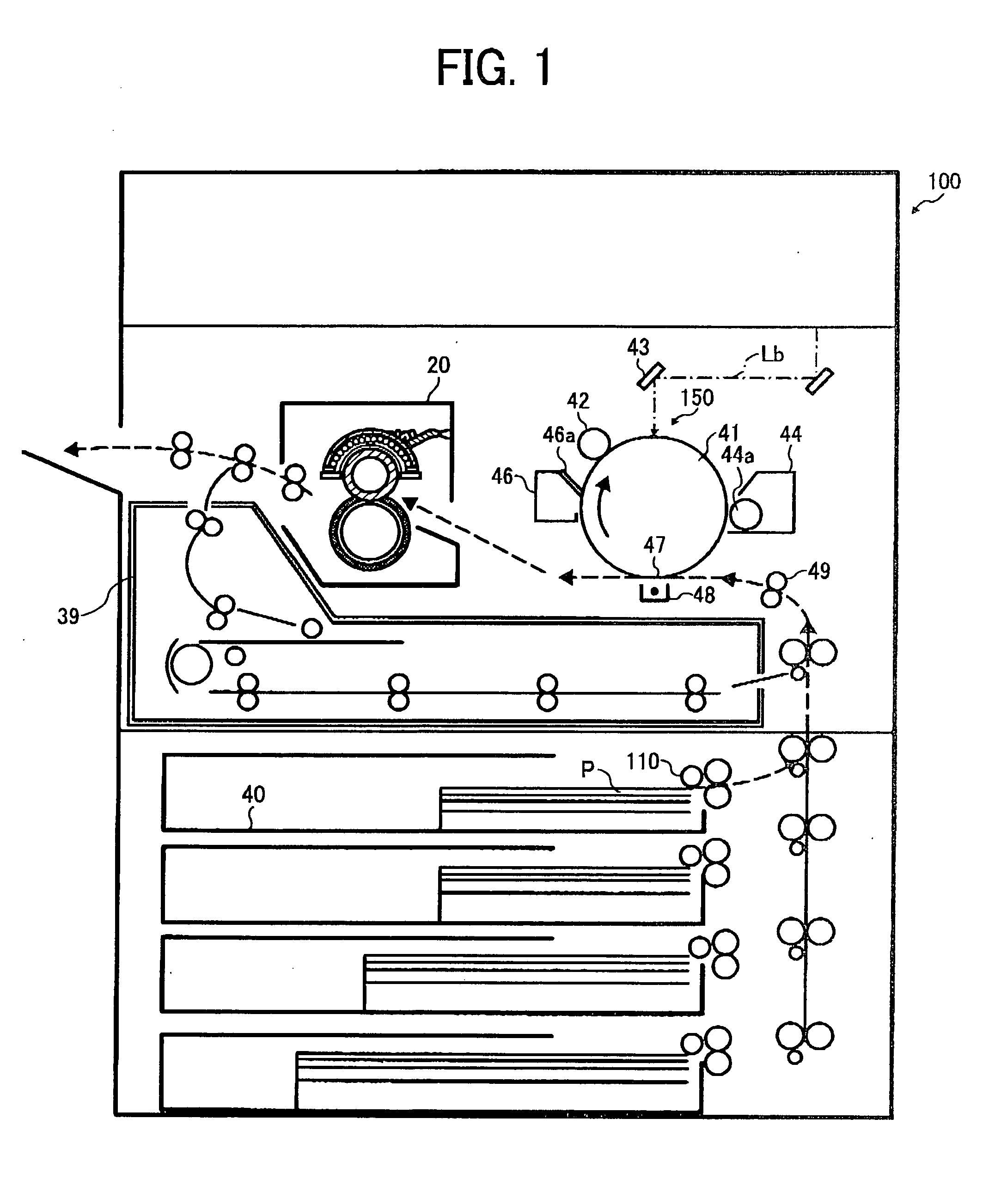
[0043]FIG. 1 is a schematic diagram illustrating one exemplary structure of an image forming apparatus 100 according to an exemplary embodiment of the present invention.

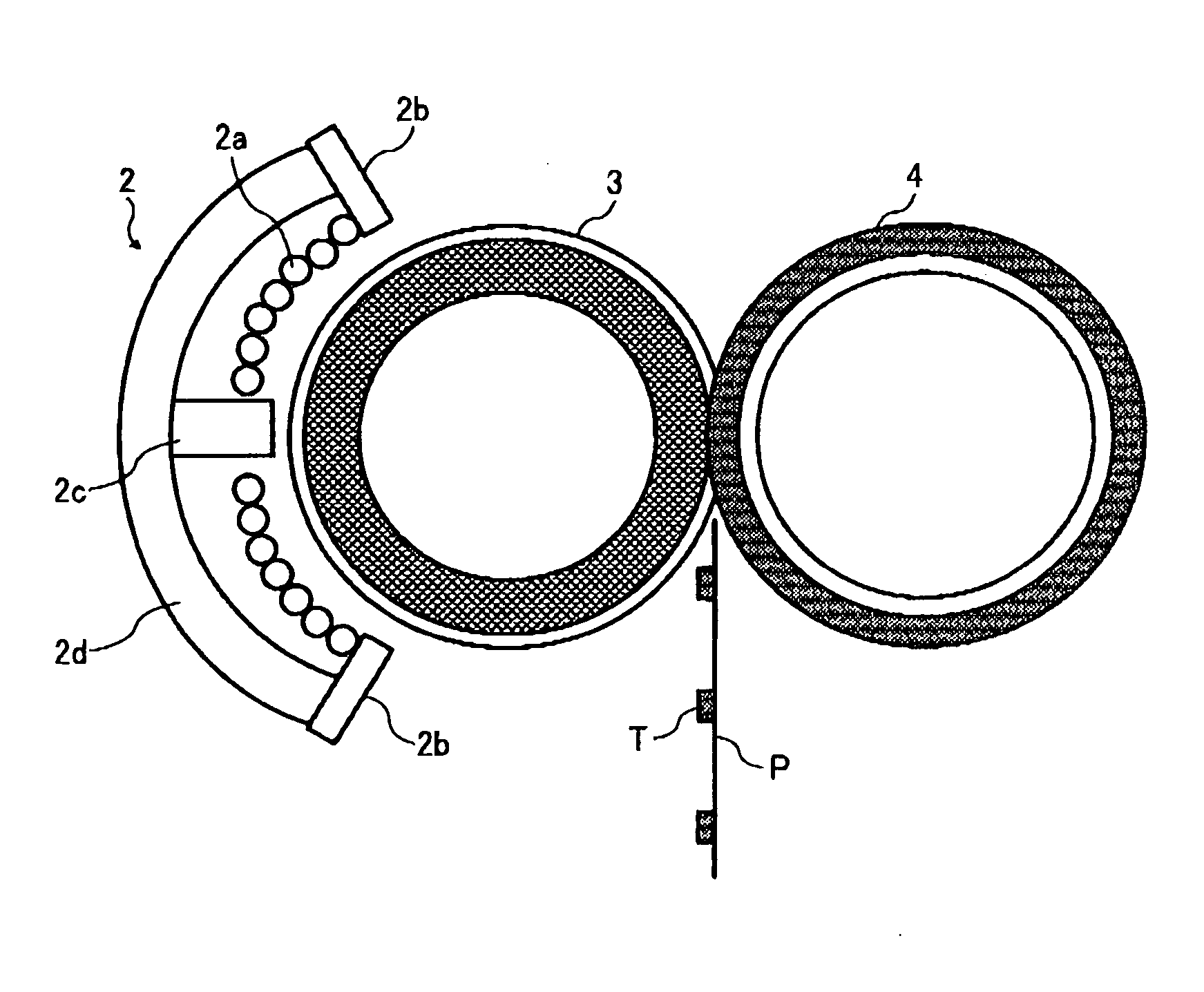
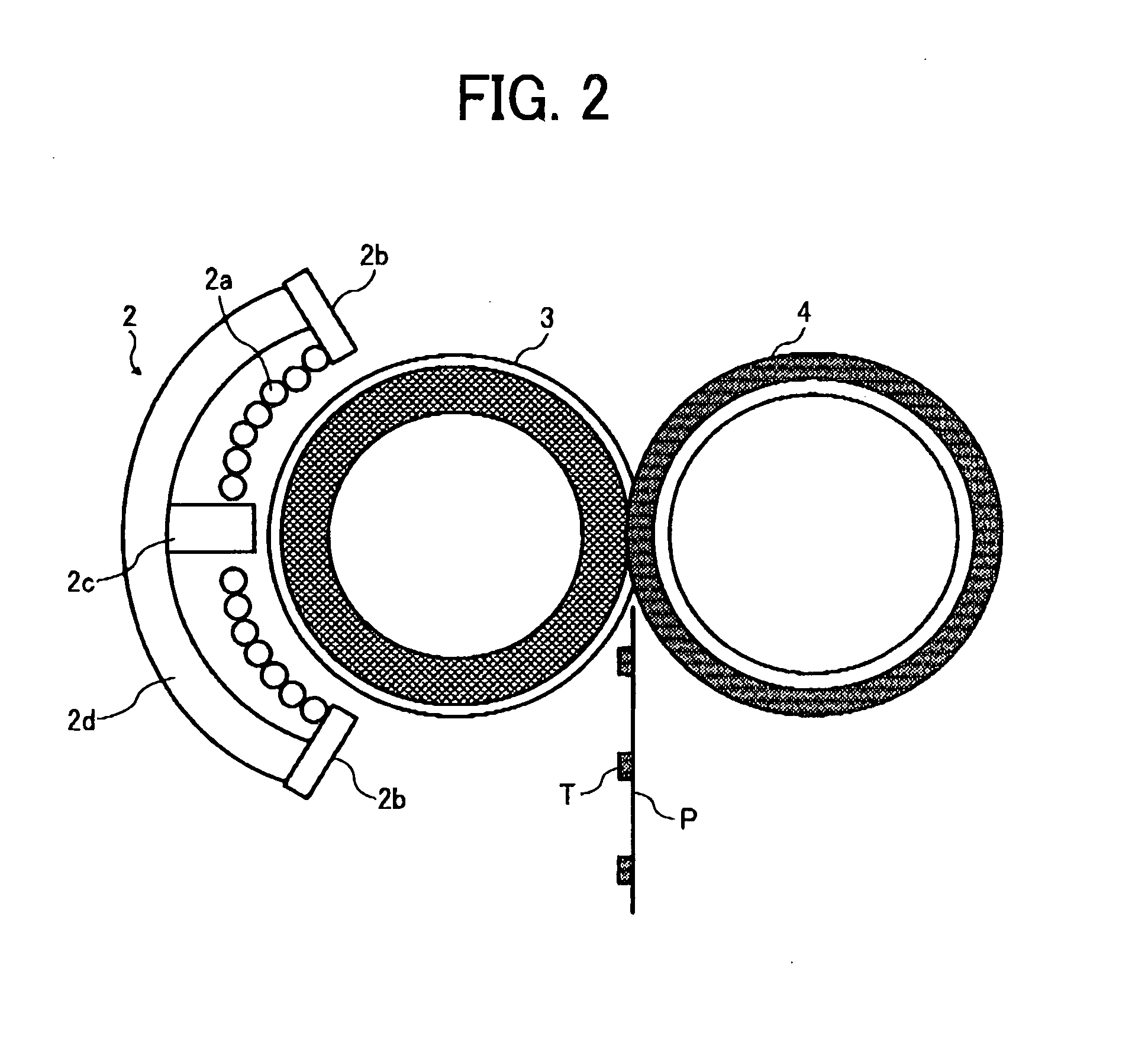
[0044]The image forming apparatus 100 of FIG. 1 includes at least an electrophotographic photoreceptor 41 (hereinafter referred to as a photoreceptor), a charger 42, a mirror 43, a developing unit 44, a transfer unit 48, a cleaning unit 46 and so forth.

[0045]The photoreceptor 41 shown in FIG. 1 is an example of an image bearing member and is a rotary member having a drum shape. Surrounding the photoreceptor 41 there are provided: the charger 42 including a charging roller; the mirror 43 serving as one part...

second exemplary embodiment

[0083]Referring now to FIG. 4, there is provided a cross-sectional view illustrating a second exemplary embodiment. FIG. 4 illustrates one example of a layer integrally including the magnetic shunt layer 3D and the heat generating layer 3F.

[0084]The same reference numerals are given to constituent elements corresponding to the constituent elements shown in FIG. 3A, and redundant descriptions thereof will be omitted unless otherwise stated.

[0085]It should be noted that the antioxidant layer in FIG. 4 includes one layer, and is denoted as 3E in FIG. 4.

[0086]One or more embodiments of the present invention may be employed not only in the image forming apparatus described above, but also in a monochrome-image forming apparatus and an image forming apparatus for producing a color image.

[0087]Furthermore, elements and / or features of different exemplary embodiments may be combined with each other and / or substituted for each other within the scope of this disclosure and appended claims.

[008...


PUM


Abstract

An image forming apparatus includes a fixing device to fix a toner image on a recording medium by applying heat. Such a fixing device includes at least a magnetic flux generator, a heat generating roller, a magnetic shunt layer, and a protective layer. The magnetic flux generator is configured to generate magnetic flux. The heat generating roller including a heat generating layer is configured to generate heat by the magnetic flux. The magnetic shunt layer may be formed independently of the heat generating layer. The protective layer is provided on an inner surface of the magnetic shunt layer and configured to cover a crack formed in the magnetic shunt layer during fabrication of the magnetic shunt layer. An image is fixed onto the recording medium by the heat from the heat generating roller. Alternatively, the magnetic shunt layer may be integrally provided with the heat generating layer.

Description

CROSS-REFERENCE TO RELATED APPLICATION[0001]This patent application is based on and claims priority pursuant to 35 U.S.C. §119 from Japanese Patent Application No. JP2007-077017, filed on Mar. 23, 2007 in the Japan Patent Office, the entire contents of which is hereby incorporated herein by reference.BACKGROUND OF THE INVENTION[0002]1. Field of the Invention[0003]Exemplary aspects of the present invention generally relate to a fixing device and an image forming apparatus including the same, and more particularly, to a fixing device using electromagnetic induction heating as a fixing method and an image forming apparatus including the same.[0004]2. Description of the Background Art[0005]Image forming apparatuses such as copiers, printers, facsimile machines, and multi-function machines output an image by transferring a visible image, such as a toner image borne on an image carrier, onto a recording medium, for example, a recording medium such as a sheet of paper or the like.[0006]Whe...

Claims


Application Information

Patent Timeline
Patent Type & Authority Applications(United States)
IPC IPC(8): G03G15/20
CPCG03G15/2053G03G15/2007
Inventor UENO, SATOSHIISHII, KENJIOGAWA, TADASHIITO, AKIKOSEO, HIROSHI
Owner RICOH KK
Why Eureka
Try Eureka