Supercharge Your Innovation With Domain-Expert AI Agents!

Combine harvester with suction fan

Inactive Publication Date: 2008-09-25
CLAAS SELBSTFAHRENDE ERNTEMASCHINEN GMBH
View PDF18 Cites 13 Cited by
  • Summary
  • Abstract
  • Description
  • Claims
  • Application Information

AI Technical Summary

Benefits of technology

The present invention provides a suction fan for a combine harvester that can convey a stream of material out of the cleaning device and spread it on the ground. This fan has several advantages, including the fact that it can utilize the energy of the material and compressed air flow, reducing the number of working units required. Additionally, the fan can be designed to transfer the material to a spreader, allowing for even greater spreading widths. A rotating spreader or a spreader cover can be used to evenly distribute the material on the ground. The fan also produces a consistent flow of intake air across its width, resulting in improved cleaning efficiency. The invention also includes a straw chopper and a spreader for chopped material, as well as a combine harvester with a cleaning device and a suction fan.

Problems solved by technology

The disadvantage of this known suction fan is the fact that the energy in the intake air flow that is created is used only to transport a quantity of crop material out of the machine housing into the suction fan, and two separate compressed air cleaning systems must be provided for the cleaning device.

Method used


Image

  • Combine harvester with suction fan
  • Combine harvester with suction fan
  • Combine harvester with suction fan

Examples


Embodiment Construction

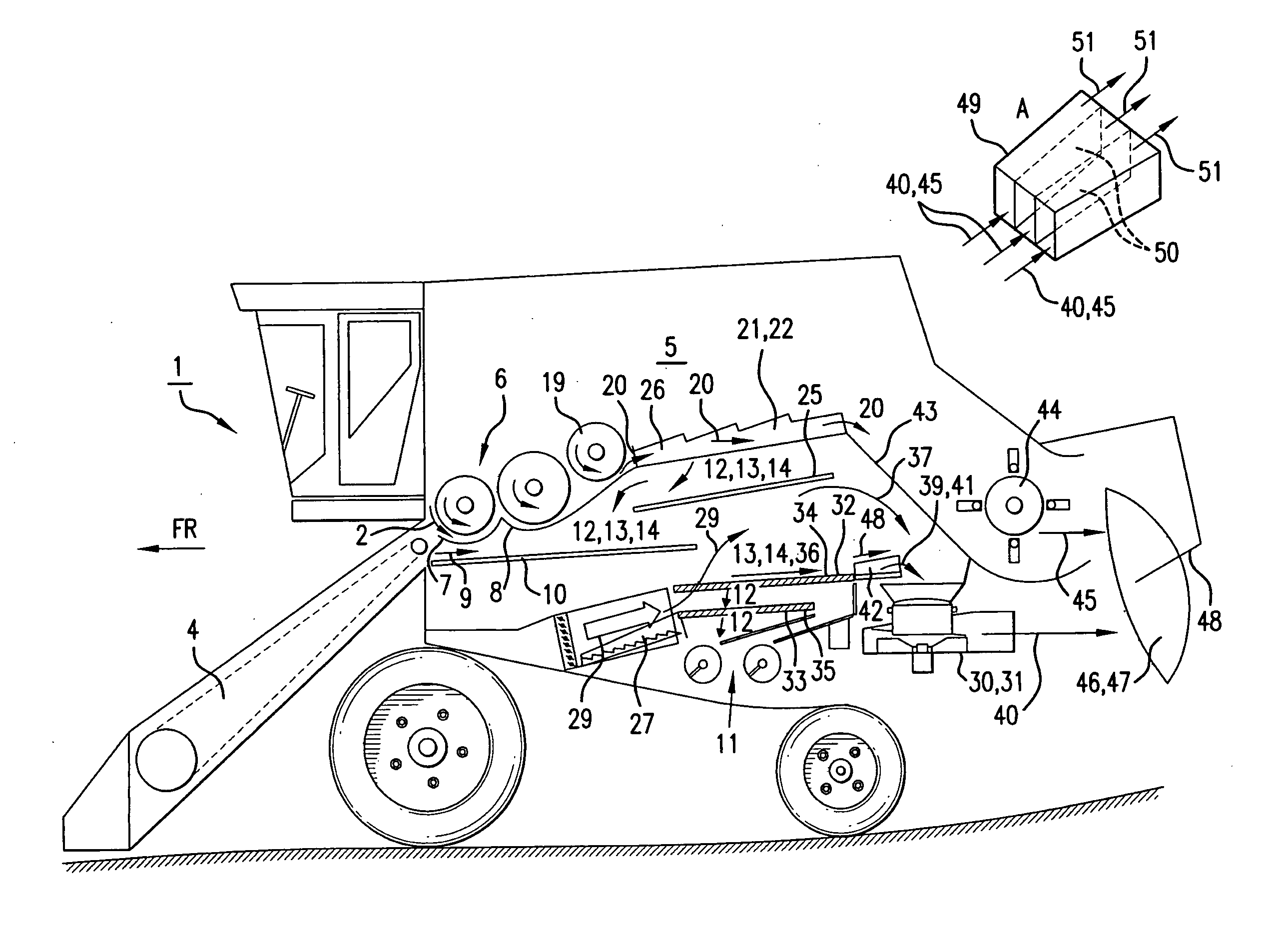
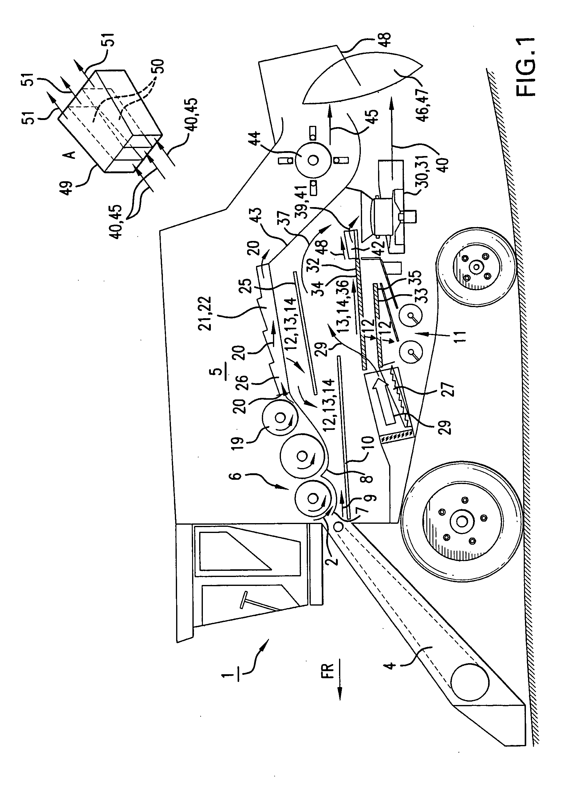
[0025]FIG. 1 shows an agricultural working machine designed as a combine harvester 1. Crop material 2 is initially taken up by header 3, which conveys crop material 2 to a feed rake 4 located on the front of combine harvester 1. Feed rake 4 transfers crop material 2 to threshing mechanism 6 located in machine housing 5. Threshing mechanism 6 processes crop material 2 intensively, so that the grain is released from crop material 2. A grain-chaff mixture 9, which is composed mainly of grain, is separated at threshing and separating grates 7, 8 of threshing mechanism 6, travels via grain pan 10 to cleaning device 11, to separate grain 12 from the non-grain components, i.e., stalk parts 13 and chaff parts 14.

[0026]In the rear region, an impeller 19 which rotates in the counterclockwise direction is assigned to threshing mechanism 6; impeller 19 catches crop material 20—which is composed mainly of threshed-out stalks—and conveys it to a separating unit 21, e.g., a tray-type shaker 22, wh...


PUM


Abstract

A self-propelled combine harvester has a machine housing, and a suction fan configured so as to convey at least one stream of material out of the machine housing, so that it causes the stream of material to be distributed across a spreading width.

Description

CROSS-REFERENCE TO A RELATED APPLICATION[0001]The invention described and claimed herein is also described in German Patent Application DE 10 2005 056 115.2 filed on Nov. 23, 2005. This German Patent Application, whose subject matter is incorporated here by reference, provides the basis for a claim of priority of invention under 35 U.S.C. 119(a)-(d).[0002]This application is a Continuation of U.S. patent application Ser. No. 11 / 560,183 filed Nov. 16, 2006.BACKGROUND OF THE INVENTION[0003]The present invention relates to a self-propelled combine harvester with a suction fan.[0004]Publication DE 26 20 875 makes known a combine harvester with a grain-cleaning device composed of two vertically stacked sieves and a forced draught fan, which blows from diagonally below through the sieves. A suction fan with a chaff suction box is also located over the uppermost sieve in the rear region of the machine housing. The chaff suction box intensifies the blow-through effect of the forced draught ...

Claims


Application Information

Patent Timeline
Patent Type & Authority Applications(United States)
IPC IPC(8): A01F12/44
CPCA01F12/444A01D41/1243
Inventor TEROERDE, STEFANBELLMANN, RAINERBAUMGARTEN, JOACHIMCLAES, ULRICHSCHULZ, WALDEMARNIERMANN, MARTIN
Owner CLAAS SELBSTFAHRENDE ERNTEMASCHINEN GMBH
Features
  • R&D
  • Intellectual Property
  • Life Sciences
  • Materials
  • Tech Scout
  • Unparalleled Data Quality
  • Higher Quality Content
  • 60% Fewer Hallucinations
Learn More