Reductant delivery unit for selective catalytic reduction

a technology of selective catalytic reduction and delivery unit, which is applied in the direction of valve operating means/release devices, functional valve types, machines/engines, etc., can solve the problems of damage to the injecting unit, high nitrogen oxide emissions of lean-burn engines, and difficult treatment of ammonia in pure form in the automotive environmen

Active Publication Date: 2008-10-02
CONTINENTAL AUTOMOTIVE SYST INC
View PDF9 Cites 115 Cited by
  • Summary
  • Abstract
  • Description
  • Claims
  • Application Information

AI Technical Summary

Benefits of technology

The patent describes a method to prevent urea solution (used in selective catalytic reduction for vehicles) from boiling in a delivery system. This is done by delivering urea solution to the system through a pump and controlling the pressure of the solution to prevent boiling. The method can detect when there is a diesel particulate regeneration event and respond accordingly to prevent the solution from boiling. The technical effect of this method is to ensure the efficient and safe operation of the SCR after-treatment system for vehicles.

Problems solved by technology

The technical problem addressed in this patent relates to delivering a selective catalytic reduction (SCR)-based emission treatment system for vehicles running on lean burn engines. Specifically, the issue includes ensuring efficient operation of the SCR system even at low temperatures, addressing potential issues related to freezing of the urea solution used in the process, reducing harmful deposit formation caused by excessive heating, and optimizing fuel efficiency during vehicle operations.

Method used


Image

  • Reductant delivery unit for selective catalytic reduction
  • Reductant delivery unit for selective catalytic reduction
  • Reductant delivery unit for selective catalytic reduction

Examples


Embodiment Construction

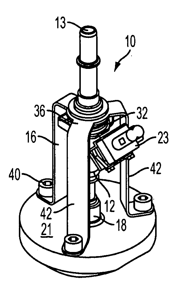
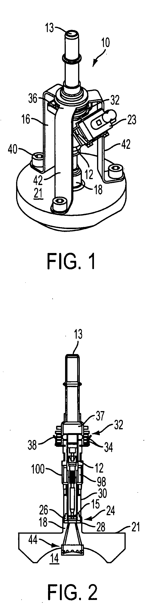
[0033]With reference to FIG. 1, a reductant delivery unit (RDU) for the delivery of AUS-32 to the engine exhaust is shown, generally indicated at 10, in accordance with an embodiment of the invention. The RDU 10 is used in SCR exhaust after-treatment systems on vehicles.

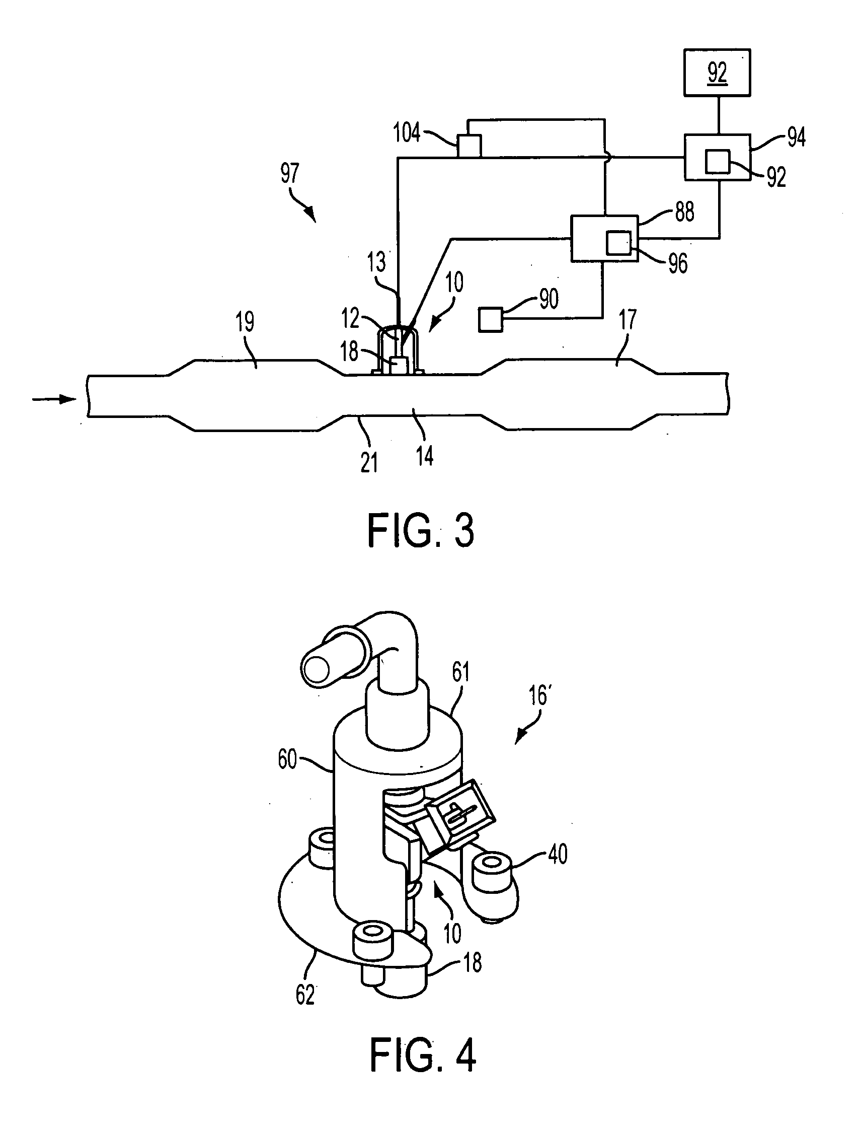
[0034]A feature of the RDU 10 is incorporation of the fluid metering and fluid preparation functions in the same unit. In order to accomplish this, the unit must be “close-coupled” to the exhaust, which implies exposure to a more hostile environment, particularly of the metering function which previously had been held outside of this environment remote from the exhaust system. The metering function is performed by a specially adapted and packaged solenoid fluid injector 12. The injector 12 also provides the spray preparation of the fluid in the exhaust path 14 (FIGS. 2 and 3) that is upstream of an SCR catalytic converter 17 (FIG. 3). More particularly, the injector 12 is mounted in the exhaust path 14 preferably bet...


PUM


Abstract

A reductant delivery unit (10) is provided for selective catalytic reduction (SCR) after-treatment for vehicles. The unit includes a solenoid fluid injector (10) constructed and arranged to be associated with an exhaust gas flow path (14) upstream of a SCR catalytic converter (17). The fluid injector has a fluid inlet (13) and a fluid outlet (15) with the fluid inlet being constructed and arranged to receive a source of urea solution and the fluid outlet being constructed and arranged to communicate directly with the exhaust flow path so as to control injection of urea solution into the exhaust gas flow path. An interface (24) is constructed and arranged to couple the fluid injector to the gas flow path. The interface defines a thermal barrier constructed and arranged to decoupled a body of the injector from exposure to heat in the exhaust gas flow path.

Description


Claims


Application Information

Patent Timeline
Owner CONTINENTAL AUTOMOTIVE SYST INC
Why Eureka
Try Eureka