Magnetic refrigerating device and magnetic refrigerating method

Inactive Publication Date: 2008-10-02
KK TOSHIBA
View PDF9 Cites 64 Cited by
  • Summary
  • Abstract
  • Description
  • Claims
  • Application Information

AI Technical Summary

Benefits of technology

[0023]It is an object of the present invention, in view of the above-described problems relating to the magnetic refrigeration device using the permanent magnet as a magnetic field-generating means, to provide a small and simple magnetic ref

Problems solved by technology

However, in the refrigeration technique using the gas compressing and expanding cycle such as a chlorofluorocarbon (CFC) or hydrochlorofluorocarbon (HCFC) or hydrofluorocarbon (HFC) gas, there are some problems relating to the ozone layer destruction or the global warming caused by the environmental exhaust of those gasses.
However, the magnetic refrigeration system is grown in size.
The intended magnetic refrigeration requires the cryogenic condition of extreme lower temperature environment than the intended refrigerating environment, which is paradox in engineering application.
Therefore, the magnetic refrigeration system becomes complicated, grows in siz

Method used


Image

  • Magnetic refrigerating device and magnetic refrigerating method
  • Magnetic refrigerating device and magnetic refrigerating method
  • Magnetic refrigerating device and magnetic refrigerating method

Examples


Embodiment Construction

[0043]Hereinafter, the present invention will be described in detail with reference to the drawings.

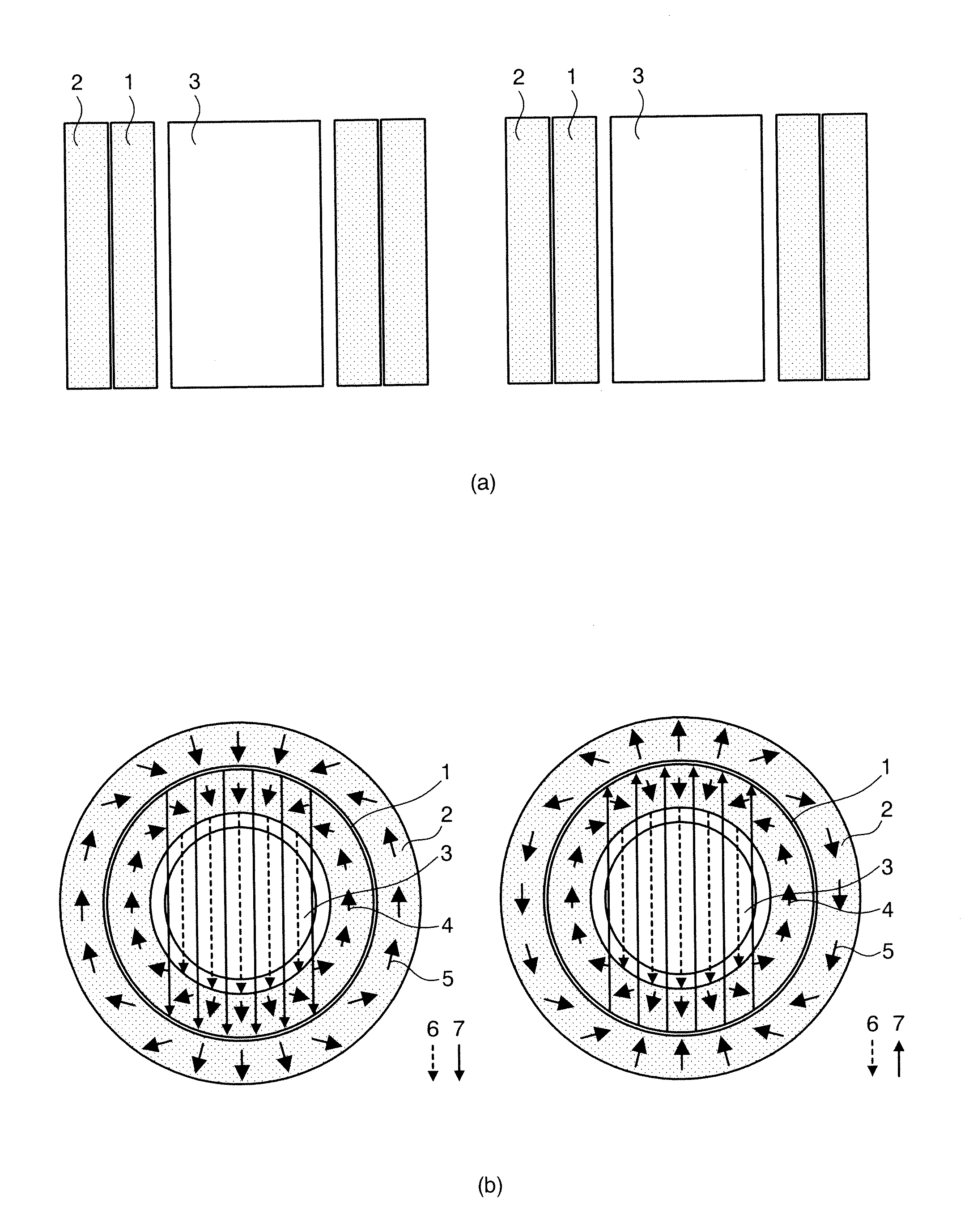
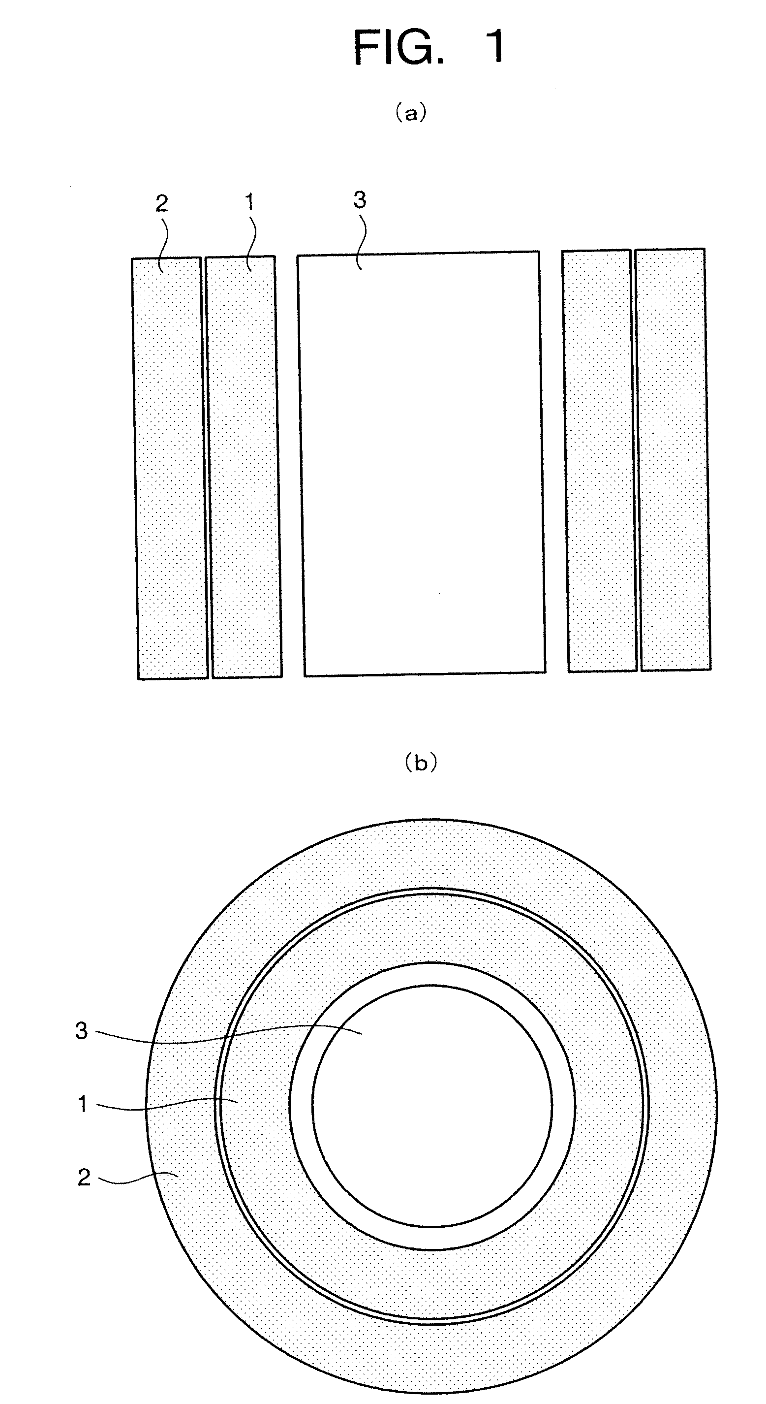
[0044]FIG. 1 is a schematic view illustrating a portion of the magnetic refrigerating device according to an embodiment of the present invention. FIG. 1(a) is directed at the cross section of the magnetic refrigerating device, and FIG. 1(b) is directed at the top plan view of the magnetic refrigerating device. In the present specification, like or corresponding components are designated by the same reference numerals.

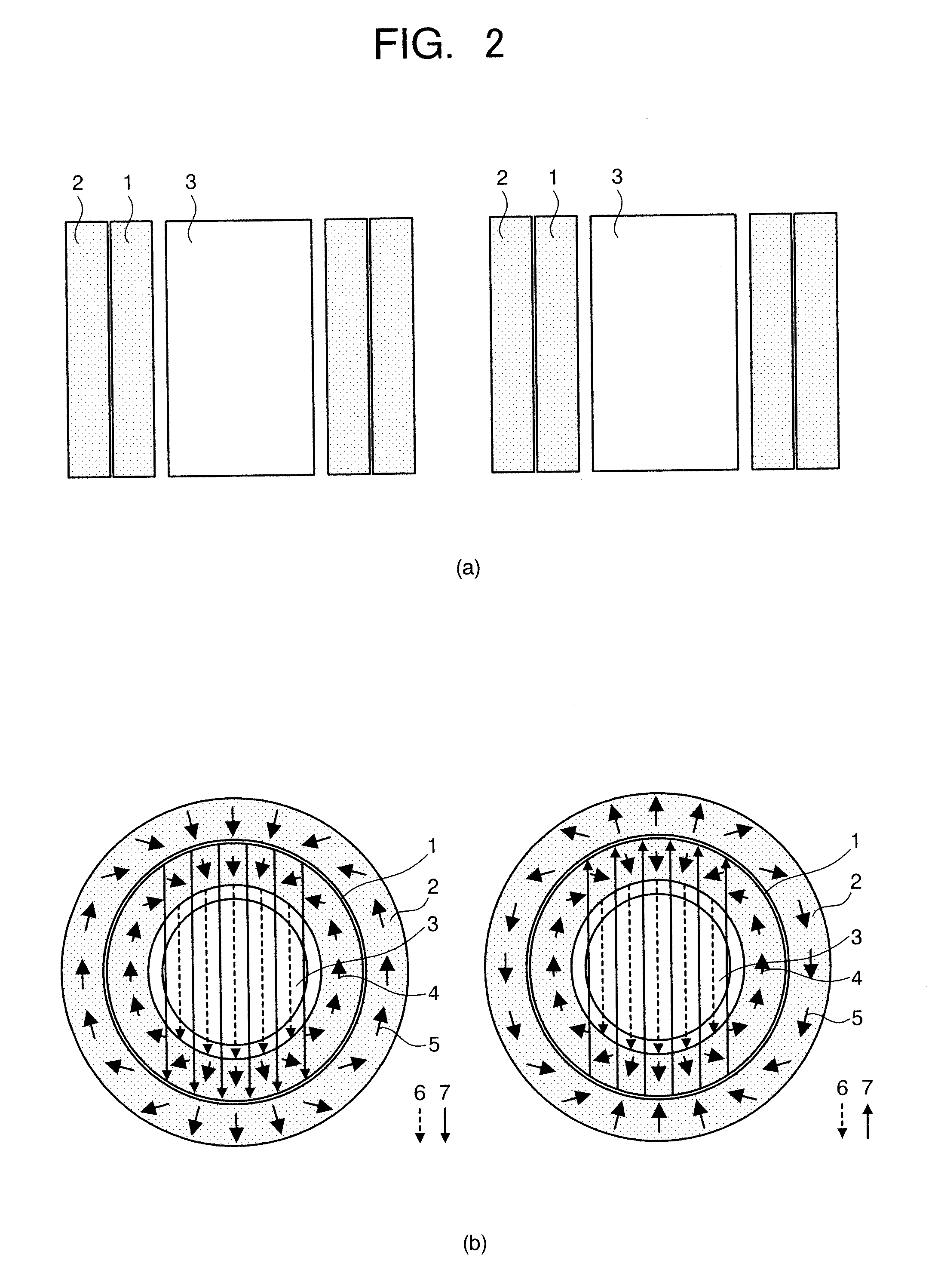
[0045]In FIG. 1, the reference numeral “1” designates an inner Halbach type magnet and the reference numeral “2” designates an outer Halbach type magnet. The inner Halbach type magnet is coaxially disposed in the outer Halbach type magnet so as to form the double-structured Halbach type magnet. The reference numeral “3” designates a magnetic refrigerant which may be accommodated into a container (not shown).

[0046]In this embodiment, since the intended heat transfer is car...


PUM


Abstract

A magnetic refrigerating device includes: at least one set of double-structured Halbach type magnet including a ring-shaped inner Halbach type magnet and a ring-shaped outer Halbach type magnet which are coaxially arranged one another so that a magnetic field generated by the inner Halbach type magnet is superimposed with a magnetic field generated by the outer Halbach type magnet; a magnetic refrigerant or a magnetic refrigeration working chamber including the magnetic refrigerant therein disposed in a bore space of the inner Halbach type magnet; and a rotating mechanism to rotate the outer Halbach type magnet while the inner Halbach type magnet is stationed.

Description

CROSS-REFERENCE TO RELATED APPLICATIONS[0001]This application is based upon and claims the benefit of priority from the prior Japanese Patent Application No. 2006-265833, filed on Sep. 28, 2006; the entire contents of which are incorporated herein by reference.BACKGROUND OF THE INVENTION[0002]1. Field of the Invention[0003]The present invention relates to a magnetic refrigeration device and a magnetic refrigeration method which utilize a permanent magnet as a magnetic field-generating means and particularly, to a magnetic refrigeration device and a magnetic refrigeration method which can reduce heat flow into the magnetic refrigeration working chamber when the magnetic refrigeration material is magnetizing and demagnetizing.[0004]2. Description of the Related Art[0005]When the intensity of magnetic field to be applied is changed for a certain magnetic material, the temperature of the magnetic material also changes, which is called as a “magneto-caloric effect”. Physically, the degre...

Claims


Application Information

Patent Timeline
IPC IPC(8): F25B21/00
CPCF25B21/00F25B2321/002F25B2321/0022F25B2321/0023Y02B30/66Y02B30/00
Inventor SAITO, AKIKOKOBAYASHI, TADAHIKOTSUJI, HIDEYUKIIWASAKI, HIDEOHISANO, KATSUMIKOGA, AKIHIROKASAHARA, AKIHIROTAKAHASHI, TAKUYA
Owner KK TOSHIBA
Why Eureka
Try Eureka