Pool cleaner with high pressure cleaning jets

a technology of high-pressure cleaning and cleaning jets, which is applied in the direction of gymnasiums, buildings, construction, etc., can solve the problems of affecting the efficiency of cleaning, and affecting the cleaning effect of the apparatus, so as to improve the cleaning ability of the apparatus.

Inactive Publication Date: 2008-10-02
AQUA PRODS
View PDF10 Cites 84 Cited by
  • Summary
  • Abstract
  • Description
  • Claims
  • Application Information

AI Technical Summary

Benefits of technology

[0006]This invention relates to an improvement in the cleaning methods and apparatus that overcome the above-described shortcomings of pool cleaners of the prior art, whether hand-powered or of the self-propelled and robotic type. The introduction of water jets under the cleaner body, directed inboard and generally toward its center from its sides, agitates and lifts the dirt and debris, which is then moved toward the one or more baseplate intake ports, to greatly enhance the cleaning ability of the apparatus. The suspended dirt and debris become semi-buoyant under the force and turbulence of the jetted water.

Problems solved by technology

One of the most common problems that occurs in the disrupting of the efficient operation and pre-determined movement patterns of an automated swimming pool cleaner are discontinuities in and obstacles protruding from the bottom surface of the pool.
When a self-propelled cleaner encounters and attempts to pass over or around an obstacle, it can become immobilized, particularly if the obstacle engages the opening of the vacuum intake.
However, the higher the intake, the less effective the vacuuming becomes.
Debris is also left behind when the cleaner is moving rapidly.
The result is that it may take many hours to clean an average size swimming pool.
The intake adapters are also subject to being immobilized on steps or other protruding obstacles.
A further general problem of effectively and efficiently cleaning the bottom surface exists where the dirt and debris is heavy and / or when the pool has not been regularly cleaned and the movement of water into the intake ports in the bottom or baseplate of the pool cleaner is not sufficient to create the required turbulence at the surface to disturb and lift the dirt and debris into suspension so that it can be drawn to the intake port.

Method used


Image

  • Pool cleaner with high pressure cleaning jets
  • Pool cleaner with high pressure cleaning jets
  • Pool cleaner with high pressure cleaning jets

Examples


first embodiment

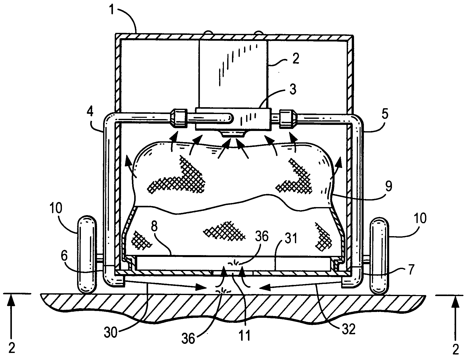
[0053]Referring to FIG. 1, a self-propelled robotic swimming pool cleaner implementing the present invention is shown, which includes a housing 1, an electric motor 2, a centrifugal pump 3, connecting tubes 4 and 5, jet nozzle elbows 6 and 7, filter bag holder 8, filter bag 9 and wheels 10 supporting the housing 1. The self-propelled swimming pool cleaner can include features known to the prior cleaning apparatus which are moved by the directional control of one or more water jets and valves, such as the apparatus and methods described in commonly assigned U.S. Publication No. 2007 / 0101521 and U.S. Pat. Nos. 7,316,751, 7,165,284, 6,971,136, 6,742,613, 6,412,133, the disclosures all of which are incorporated herein by reference in their entirety.

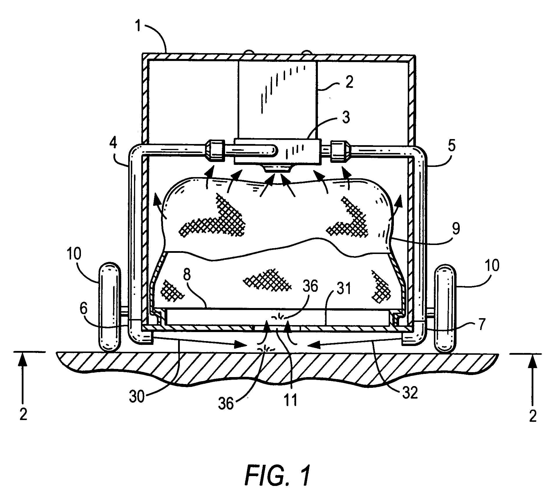
[0054]As further illustrated in FIG. 2, the water jets 30, 32, are supplied by the centrifugal pump 3 and discharged by the jet nozzles 6, 7, respectively, are directed toward the dirt and debris 36 on the pool surface below the baseplate 31....

second embodiment

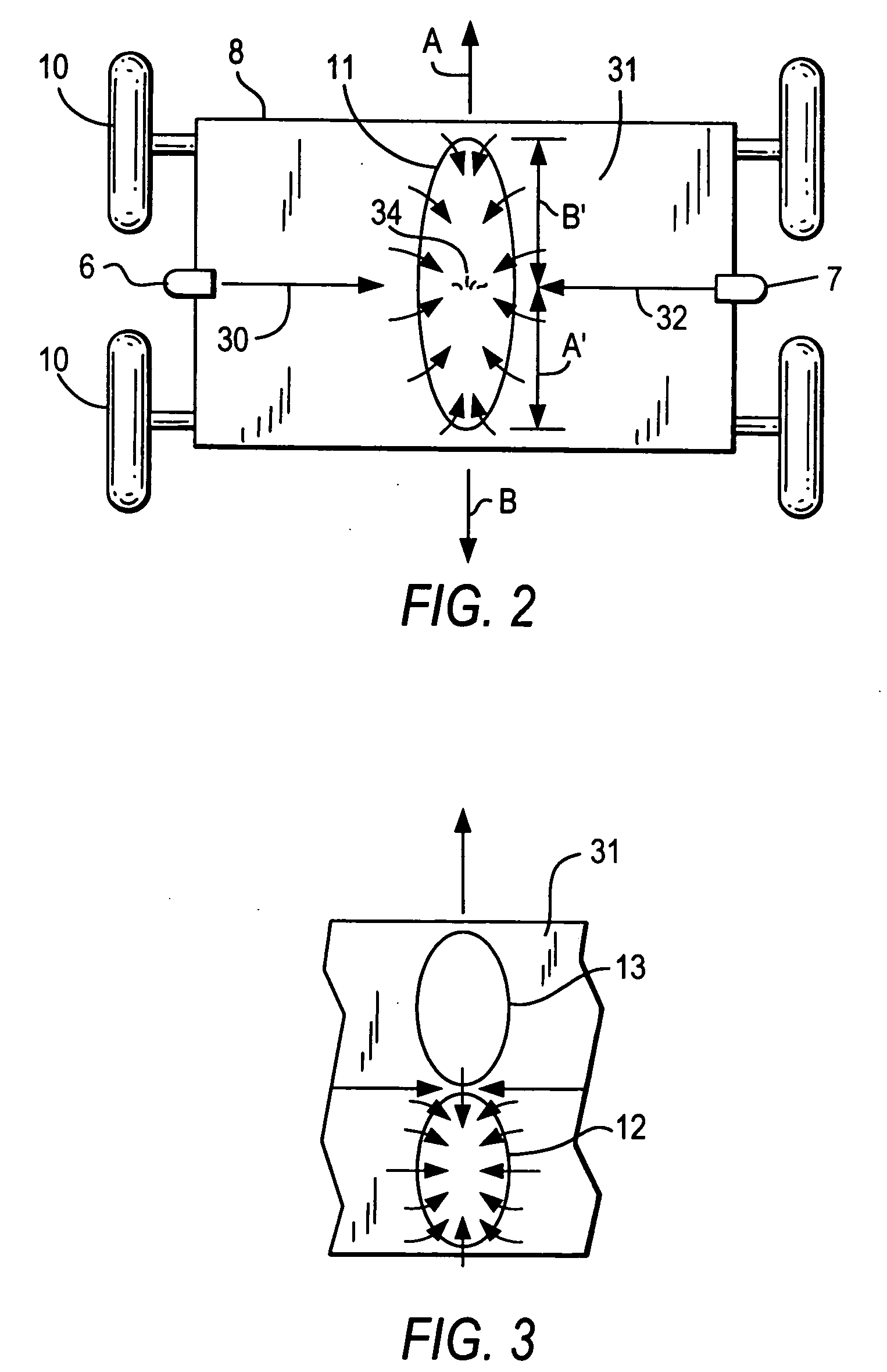
[0057]In the second embodiment shown in FIG. 3, the one long intake opening of the intake 11 of FIG. 2 is replaced by two smaller openings 12 and 13, one of which is always closed, as by a solenoid switch or other means. Thus, the speed of the intake stream as indicated by the arrows can be doubled.

[0058]With reference to FIG. 4, there is shown yet another embodiment in which swiveling elbow jet nozzles 14 and 15 are equipped with fins 16 and 17, respectively, which automatically change the positions of the nozzles due to the force of the water, or water resistance, as the cleaner changes direction, to thereby always point to the upstream end of the intake 18. In the angular arrangement of the jet nozzles 14, 15 illustrated in FIG. 4, water is discharged at a predetermined pressure to move the debris 36 at a velocity that greatly reduces the relative speed between the debris 36 and the cleaner optimally to zero. This permits the cleaner to move at a relatively higher speed while the...


PUM


Abstract

A pool cleaning apparatus includes a housing and a pump for drawing water and debris through an intake port into a filter. A jet-valve housing having a jet valve flap is mounted over the pump to direct a propulsion jet stream from the pump to move the cleaner in a forward direction. A cleaning nozzle is mounted over each of the front and rear portions of the housing, and a pressurized water jet stream is directed at a first pool surface beneath the cleaner through the front end nozzle while moving in a forward direction. When the cleaner engages a second pool surface substantially perpendicular to the first surface, propulsion outlets of the jet valve housing are partially closed to redirect a portion of the propulsion jet stream to the front-end nozzle to lift the front end of the cleaner off the first surface. When the front end of the cleaner disengages from contact with the second surface, the propulsion outlets open to permit the propulsion jet stream to propel the cleaner along the second surface.

Description

CROSS REFERENCES TO RELATED APPLICATIONS[0001]This application is related to application Ser. No. ______ co-filed ______ (Attorney Docket No. 209,578), and is related to application Ser. No. 11 / 233,595, filed Sep. 22, 2005, now U.S. Pat. No. 7,316,751, which is a division of application Ser. No. 10 / 272,754, filed Oct. 17, 2002, now U.S. Pat. No. 6,971,136; and is a continuation-in-part of application Ser. No. 11 / 606,809, filed Nov. 29, 2006, which is a divisional of application Ser. No. 10 / 793,447, filed Mar. 3, 2004, now U.S. Pat. No. 7,165,284, which is a division of application Ser. No. 10 / 109,689, filed Mar. 29, 2002, now U.S. Pat. No. 6,742,613, which is a division of application Ser. No. 09 / 237,301, filed Jan. 25, 1999, now U.S. Pat. No. 6,412,133; the disclosures all of which are incorporated herein by reference in their entireties.FIELD OF THE INVENTION[0002]This invention relates to hand-powered and self-propelled pool and tank cleaners that draw water containing dirt and d...

Claims


Application Information

Patent Timeline
Patent Type & Authority Applications(United States)
IPC IPC(8): E04H4/16B08B5/00
CPCE04H4/1654
Inventor HORVATH, TIBORERLICH, GIORA
Owner AQUA PRODS
Why Eureka
Try Eureka