Decision method for dressing of welding electrodes

a technology of electrode dressing and decision method, which is applied in the maintenance of electrodes, manufacturing tools, electrode features, etc., can solve problems such as creeping into welding operations

Inactive Publication Date: 2008-10-02
GM GLOBAL TECH OPERATIONS LLC +1
View PDF2 Cites 15 Cited by
  • Summary
  • Abstract
  • Description
  • Claims
  • Application Information

AI Technical Summary

Problems solved by technology

However, it is known that variations creep into the welding operation because of electrode wear.

Method used


Image

  • Decision method for dressing of welding electrodes
  • Decision method for dressing of welding electrodes
  • Decision method for dressing of welding electrodes

Examples


Embodiment Construction

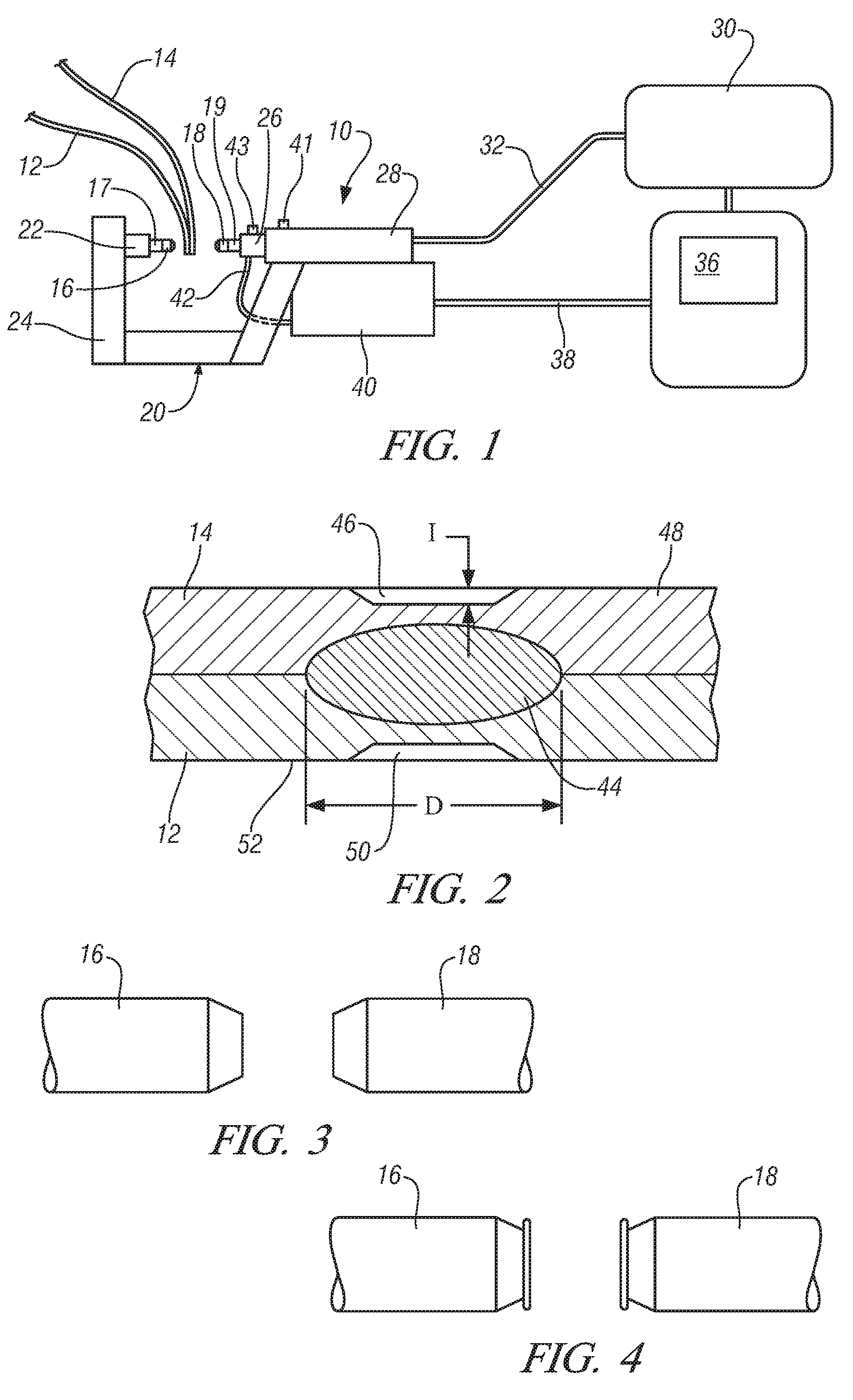
[0015]Referring to FIG. 1, a schematic illustration of a side view of a representative spot welding gun apparatus 10 is shown. In such an operation, an assembly of two or more sheet metal layers to be welded is prepared at a suitable location and transported by means, not shown, to the welding gun apparatus 10. In this example, the assembled sheets consist of sheets 12 and 14 of formable commercial steel. The assembled sheets 12 and 14 may, for example, be previously stamped inner and outer panels for a vehicle body.

[0016]The weld gun apparatus 10 includes a fixed electrode 16 mounted on a shank 17 inserted in a holder 22, which is attached to a fixed arm 24 of a welding gun arm 20. A movable electrode 18 is mounted on a shank 19 and inserted in a holder 26 carried in a servomotor drive 28. Servomotor drive 28 is adapted to axially move the movable electrode 18 into clamping engagement with the sheet 14 and press and clamp the sheet 12 into clamping engagement with the sheet 12.

[001...


PUM

PropertyMeasurementUnit
currentaaaaaaaaaa
thickaaaaaaaaaa
depthaaaaaaaaaa

Abstract

A method is provided for determining that the electrodes of an electric resistance welder are in need of replacement and dressing includes monitoring the rate at which the depth of the weld indentation caused by the electrode changes during the progressive wearing of the electrodes during the making of successive welds. The electrodes are then dressed when it is determined that the rate of change of the depth of the weld indentation formed by the electrodes has substantially leveled off to a stable depth of indentation.

Description

FIELD OF THE INVENTION[0001]The present invention relates to a method for determining the need to dress the tip of welding electrodes in an electric resistance spot welding process.BACKGROUND OF THE INVENTION[0002]The construction of automotive bodies and other manufactured products often requires the formation of many uniformly sized electrical resistance spot welds. The welds are made by bringing assemblies of sheet metal parts to a welding station where a computer controlled robot, or other welding machine, systematically and sequentially forms a series of spot welds to attach the sheet metal parts of the sheet metal assembly.[0003]The welding is performed using a weld gun typically having copper or copper alloy welding electrodes. One electrode is a fixed electrode and the other electrode is a movable electrode. The electrodes are axially aligned in opposition to each other, at a specified spot weld site, and the movable electrode is advanced to clamp and press the sheets agains...

Claims


Application Information

Patent Timeline
Patent Type & Authority Applications(United States)
IPC IPC(8): B23K31/12
CPCB23K11/3063
Inventor LIN, ZHONGQINWANG, PEI-CHUNGLAI, XINMINZHANG, YANSONGCHEN, GUANLONGSUN, PETER C.
Owner GM GLOBAL TECH OPERATIONS LLC
Why Eureka
Try Eureka