Piezoelectric actuator, method of manufacturing same, and liquid ejection head

a technology of piezoelectric actuator and actuator body, which is applied in the direction of generator/motor, device material selection, printing, etc., can solve the problems of inability to control the volume of ink that is ejected from the nozzle, the diaphragm is not visible, and the long-term durability cannot be guaranteed. , to achieve the effect of reducing the deformation of the supporting substrate, reducing the film stress in the piezoelectric body, and high precision

Inactive Publication Date: 2008-10-02
FUJIFILM CORP
View PDF11 Cites 5 Cited by
  • Summary
  • Abstract
  • Description
  • Claims
  • Application Information

AI Technical Summary

Benefits of technology

[0020]The present invention was devised in view of the aforementioned circumstances, an object thereof being to provide a piezoelectric actuator, a method of manufacturing same, and a liquid ejection head that can reduce either the film stress in piezoelectric bodies formed onto a supporting substrate and the deformation of the supporting substrate, without restricting the material of the support substrate.
[0021]In order to attain the aforementioned object, the present invention is directed to a piezoelectric actuator comprising: a supporting substrate; a thermal stress controlling layer which is formed on the supporting substrate; and a piezoelectric body which is formed as a film onto the thermal stress controlling layer on the supporting substrate at a higher temperature than room temperature, wherein the thermal stress controlling layer reduces a film stress induced by formation of the piezoelectric body.
[0022]In the case in which no thermal stress controlling layer is interposed between the supporting substrate and the piezoelectric body, a thermal stress acts on the piezoelectric body when the piezoelectric body returns to normal temperature after film formation of the piezoelectric body, due to the difference between thermal expansion coefficients of the supporting substrate and the piezoelectric body, and the temperature difference between normal temperature and a temperature during film formation. In this case, a stress (compressive stress) also acts on the actual piezoelectric body. However, according to the present invention, since the thermal stress controlling layer is interposed, then the film stress in the piezoelectric body is reduced, and deformation of the supporting substrate is suppressed. Incidentally, it is considered that the stress of the piezoelectric body can be reduced by selecting a supporting substrate having a thermal expansion coefficient which is close to the thermal expansion coefficient of the piezoelectric body, but in this case, a restriction is placed on the thermal expansion coefficient of the supporting substrate, in addition to the durability, processability, and vibration characteristics (such as Young's modulus) of the supporting substrate. The present invention can increase choice flexibility of materials which can be used as the supporting substrate, without restricting the thermal expansion coefficient of the supporting substrate.

Problems solved by technology

Therefore, since the film is thin, it does not give rise to notable deformation of the diaphragm even if there is stress in the film.
(1) Since a gap arises when the diaphragm 1 is bonded to the ink chamber partitions 3, the following problems arise, consequently.a) Since the ink chambers 4 cannot be divided by the ink chamber partitions 3, then there is movement of ink between adjacently positioned ink chambers 4, and ink may gather in the gaps, thereby making it impossible to control the volume of ink that is ejected from the nozzles.b) Since regions where the diaphragm 1 is not fixed to the ink chamber partitions 3 arise, then variations occur in the displacement volume and torque, and hence image defects arise due to non-uniformities in ink ejection throughout the surface.c) Since the diaphragm 1 and the ink chamber partitions 3 can not be reliably fixed by bonding, then long-term durability cannot be guaranteed.
(2) Since deformation occurs in the diaphragm 1, then the volume of the ink chamber 4 varies, and variation may arise in the ejected ink volume even if the diaphragm 1 is driven at the same displacement volume, whereby image defects may occur due to non-uniformities in ink ejection throughout the surface.
(3) When deformation occurs in the diaphragm 1, sufficient alignment accuracy is not obtained in the subsequent process of wiring to the electrodes for driving the piezoelectric bodies 2, whereby wiring defects arise.

Method used


Image

  • Piezoelectric actuator, method of manufacturing same, and liquid ejection head
  • Piezoelectric actuator, method of manufacturing same, and liquid ejection head
  • Piezoelectric actuator, method of manufacturing same, and liquid ejection head

Examples


first embodiment

Case in which Thermal Expansion Coefficient of Diaphragm is Higher than that of Piezoelectric Body

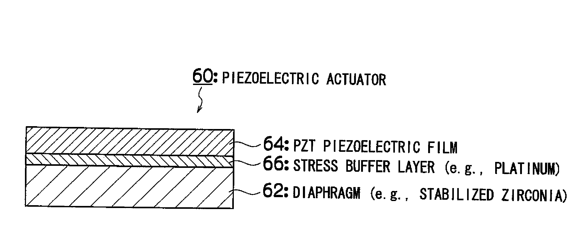
[0103]In the case in which the thermal expansion coefficient of the diaphragm is higher than that of the piezoelectric body, then a thin film made of a material having a lower thermal expansion coefficient than the diaphragm (preferably, a thermal stress controlling layer (stress buffer layer) made of a material having a lower thermal expansion coefficient than the piezoelectric body) is formed previously on the diaphragm.

[0104]FIG. 5 is a principal cross-sectional diagram of a piezoelectric actuator 60 according to a first embodiment. As shown in FIG. 5, the piezoelectric actuator 60 comprises: a stabilized zirconia substrate 62 (thermal expansion coefficient: 9.9×10⁻⁶ / ° C.) as the diaphragm; and a PZT piezoelectric film 64 (thermal expansion coefficient: 9.5×10⁻⁶ / ° C.) as the piezoelectric body. The stabilized zirconia substrate (hereinafter referred to as simply “zirconia substrate”)...

second embodiment

Case in which Thermal Expansion Coefficient of Diaphragm is Lower than that of Piezoelectric Body

[0114]In the case in which the thermal expansion coefficient of the diaphragm is lower than that of the piezoelectric body, a thin film made of a material having a higher thermal expansion coefficient than the diaphragm preferably, a thermal stress controlling layer (stress buffer layer) made of a material having a higher thermal expansion coefficient than the piezoelectric body) is formed previously on the diaphragm.

[0115]FIG. 8 is a principal cross-sectional diagram of a piezoelectric actuator 70 according to a second embodiment. As shown in FIG. 8, the piezoelectric actuator 70 comprises a silicon (Si) substrate 72 (thermal expansion coefficient: 3.5×10⁻⁶ / ° C.) as the diaphragm, and a PZT piezoelectric film 64 (thermal expansion coefficient: 9.5×10⁻⁶ / ° C.) as the piezoelectric body. A stress buffer layer 74 made of platinum (thermal expansion coefficient: 8.8×10⁻⁶ / ° C.) is formed betw...

third embodiment

Case of Diaphragm+Stress Buffer Layer+Electrode+PZT Piezoelectric Body (i.e., a Plurality of Stress Buffer Layers)

[0121]The platinum stress buffer layers 66 and 74 shown in FIG. 5 and FIG. 8 also serve as an electrode (lower electrode) for driving the PZT piezoelectric film 64, but the stress buffer layer and the electrode may be separately functionally.

[0122]FIG. 10 is a principal cross-sectional diagram of a piezoelectric actuator 80 according to a third embodiment. As shown in FIG. 10, the piezoelectric actuator 80 comprises a silicon substrate 72 (thermal expansion coefficient: 3.5×10⁻⁶ / ° C.) as the diaphragm, and a PZT piezoelectric film 64 (thermal expansion coefficient: 9.5×10⁻⁶ / ° C.) as the piezoelectric body. A stress buffer layer 82 made of nickel (thermal expansion coefficient: 13×10−6 / ° C.) and a platinum electrode 84 (thermal expansion coefficient: 8.8×10⁻⁶ / ° C.) are formed between the silicon substrate 72 and the PZT piezoelectric film 64. The stress buffer layer 82 ha...


PUM

PropertyMeasurementUnit
thicknessaaaaaaaaaa
thicknessaaaaaaaaaa
a-axis lengthaaaaaaaaaa

Abstract

The piezoelectric actuator comprises: a supporting substrate; a thermal stress controlling layer which is formed on the supporting substrate; and a piezoelectric body which is formed as a film onto the thermal stress controlling layer on the supporting substrate at a higher temperature than room temperature, wherein the thermal stress controlling layer reduces a film stress induced by formation of the piezoelectric body.

Description

BACKGROUND OF THE INVENTION[0001]1. Field of the Invention[0002]The present invention relates to a piezoelectric actuator, a method of manufacturing same, and a liquid ejection head, and more particularly to technologies that can reduce a thermal stress induced by film formation of a piezoelectric body.[0003]2. Description of the Related Art[0004]Conventionally, the principal method of manufacturing an inkjet head is a method which involves bonding a bulk polished piezoelectric body member (made of lead zirconate titanate (Pb(ZrTi)O3)(PZT), for example) and a calcined green sheet, to a diaphragm plate, by means of an adhesive. In this case, there is no need to take account of thermal stress in the piezoelectric body.[0005]Furthermore, in a method of manufacturing inkjet head described in Japanese Patent Application Publication No. 2003-309299, a piezoelectric film is grown epitaxially on an epitaxial substrate, a silicon substrate is bonded directly to the opposite side of the piezo...

Claims


Application Information

Patent Timeline
Patent Type & Authority Applications(United States)
IPC IPC(8): H01L41/053B41J2/045B41J2/055B41J2/135B41J2/14B41J2/16H01L41/09H01L41/18H01L41/187H01L41/22H01L41/257H01L41/29H01L41/314
CPCB41J2/161B41J2/1623B41J2/1626B41J2/1643Y10T29/42H01L41/0815H01L41/0973H01L41/314H01L41/319B41J2/1646H10N30/10516H10N30/2047H10N30/074H10N30/079
Inventor NIHEI, YASUKAZU
Owner FUJIFILM CORP
Why Eureka
Try Eureka