Drive signal generating apparatus, liquid ejecting apparatus, and drive signal generating method

a technology of drive signal and generating apparatus, which is applied in the direction of oscillator generator, logic circuit coupling/interface arrangement, pulse technique, etc., can solve the problems of power loss accompanies cases and the inability to achieve high-speed processing, and achieve the effect of increasing the speed of power source switching

Inactive Publication Date: 2008-10-02
SEIKO EPSON CORP
View PDF0 Cites 28 Cited by
  • Summary
  • Abstract
  • Description
  • Claims
  • Application Information

AI Technical Summary

Benefits of technology

[0008]The present invention has been devised in view of these circumstances

Problems solved by technology

A power loss accompanies cases where current amplification is performed using a transistor.
In this apparatus, the voltage level of the generated drive signal is used as a reference,

Method used


Image

  • Drive signal generating apparatus, liquid ejecting apparatus, and drive signal generating method
  • Drive signal generating apparatus, liquid ejecting apparatus, and drive signal generating method
  • Drive signal generating apparatus, liquid ejecting apparatus, and drive signal generating method

Examples


first embodiment

[0039]Regarding the Drive Signal Generating Apparatus

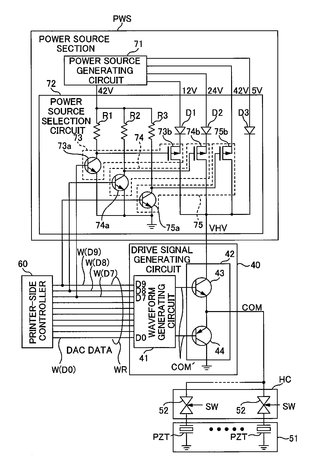
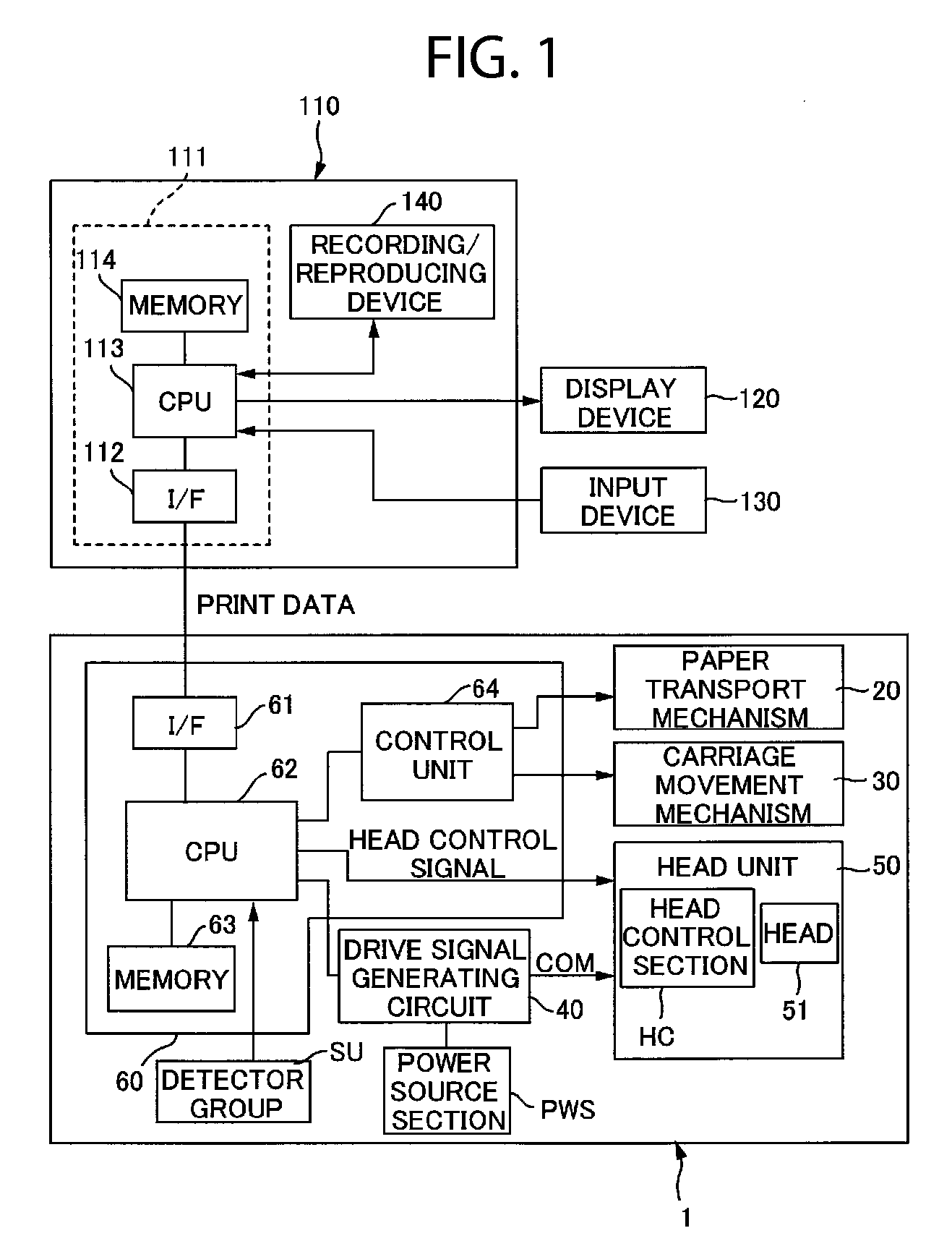
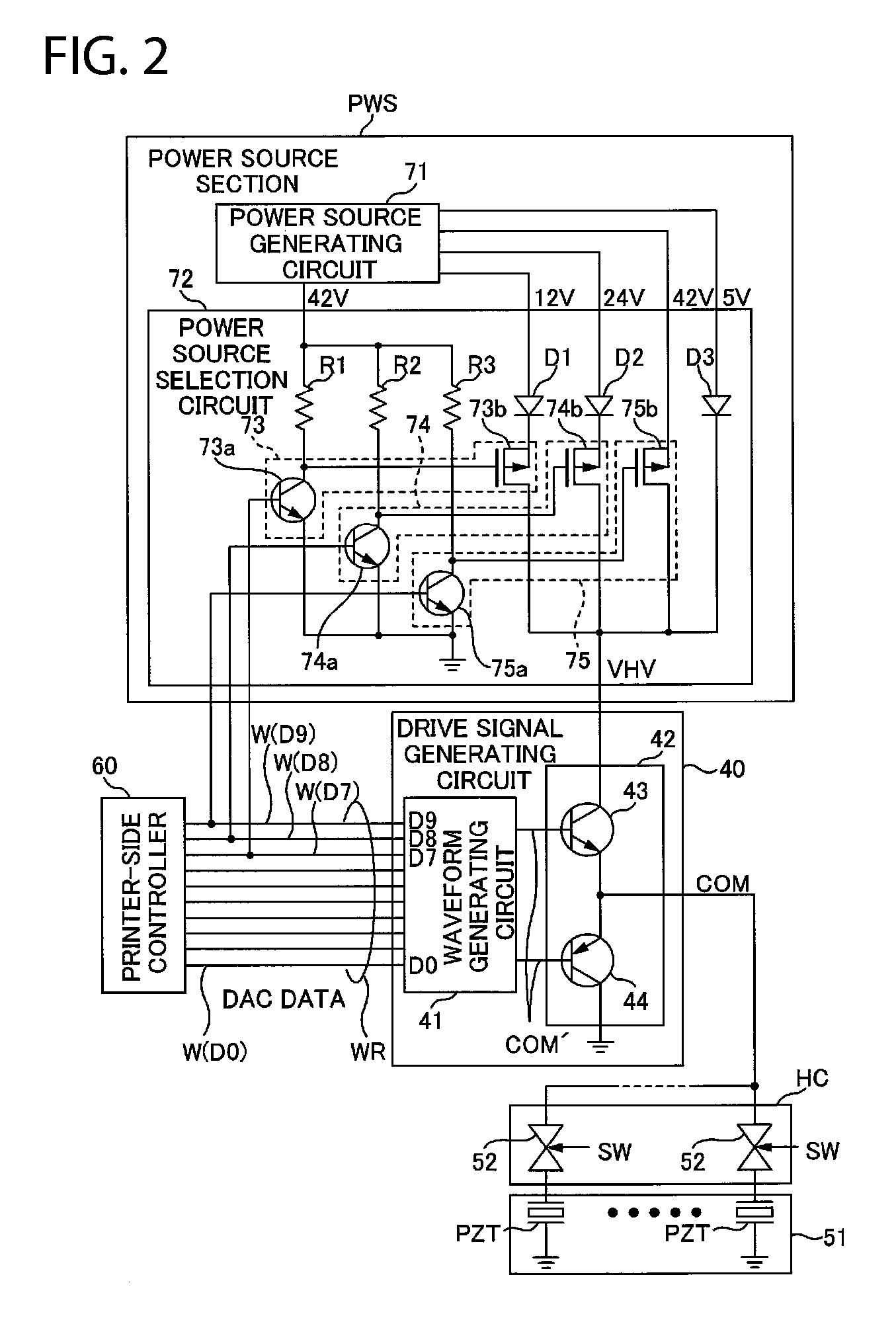
[0040]The drive signal generating apparatus generates a drive signal that is applied to an element targeted for control. The drive signal generating apparatus is incorporated for example in a liquid ejecting apparatus that ejects a liquid. Examples of liquid ejection apparatuses include printing apparatuses, color filter manufacturing apparatuses, display manufacturing apparatuses, semiconductor manufacturing apparatuses, and DNA chip manufacturing apparatuses. In liquid ejecting apparatuses such as these, a piezo element is provided for example, which serves as an element that is driven in order to cause a liquid to be ejected.

[0041]In the present specification, description is given using as an example a liquid ejecting apparatus in which the drive signal generating apparatus has been incorporated. Specifically, description is given using as an example an inkjet printer (hereinafter, also referred to simply as a “printer”) as a p...


PUM


Abstract

A drive signal generating apparatus is provided with an analog signal converting section, a current amplification section, and a power source generating section. The analog signal converting section converts digital data to an analog signal. The current amplification section is provided with a current amplification transistor and generates a drive signal by amplifying a current of the analog signal using the current amplification transistor. The power source generating section is a power source having a voltage determined based on the digital data and generates a power source to be supplied to the current amplification transistor.

Description

CROSS-REFERENCE TO RELATED APPLICATIONS[0001]The present application claims priority upon Japanese Patent Application No. 2007-83771 filed on Mar. 28, 2007, which is herein incorporated by reference.BACKGROUND[0002]1. Technical Field[0003]The present invention relates to drive signal generating apparatuses, liquid ejecting apparatuses, and drive signal generating methods.[0004]2. Related Art[0005]There are apparatuses that apply a drive signal to an element targeted for control, thereby causing the element to carry out a desired operation. For example, in an inkjet printer, which is one type of liquid ejecting apparatus, drive signals are applied selectively to piezo elements such that the piezo elements deform to eject ink.[0006]A drive signal generating apparatus that generates a drive signal such as this for example performs current amplification on an analog signal having a desired voltage variation pattern, thereby generating drive signals. A power loss accompanies cases where ...

Claims


Application Information

Patent Timeline
IPC IPC(8): B41J29/38H03K3/00
CPCB41J29/393H03K19/017581
Inventor UMEDA, ATSUSHI
Owner SEIKO EPSON CORP
Why Eureka
Try Eureka