Image projector

a projector and projector technology, applied in the field of image projectors, can solve the problems of distorted image projected onto the projection plane (projected image), difference between the resolution in the center of the screen and the resolution in the peripheral part of the screen, and high brightness in the peripheral parts of the screen, so as to achieve high-quality image and small size

Inactive Publication Date: 2008-10-02
KONICA MINOLTA OPTO
View PDF2 Cites 74 Cited by
  • Summary
  • Abstract
  • Description
  • Claims
  • Application Information

AI Technical Summary

Benefits of technology

[0012]Without causing enlargement of the projection optical system and deterioration in brightness of an image, assurance of constant speed in the scan of a light flux and suppression of a distortion in an image can be achieved. Therefore, the invention can provide the image projector capable of projecting a high-quality image while realizing small size.
[0014]Without causing enlargement of the projection optical system and deterioration in brightness of an image, assurance of constant speed in the scan of a light flux and suppression of a distortion in an image can be achieved. Therefore, the invention can provide the image projector capable of projecting a high-quality image while realizing small size.
[0017]Therefore, an object of the present invention is to provide an image projector capable of projecting a high-quality image while realizing small size.

Problems solved by technology

It is also known as a general problem that, due to such a phenomenon, brightness in peripheral parts of a screen becomes higher than that in the center of the screen and, when the modulation speed of the light source is constant, a difference occurs between the resolution in the center of the screen and the resolution in a peripheral part of the screen.
It is also known as another general problem that, when a projection method of projecting an image onto a projection plane (for example, a screen) from an oblique direction is considered, an image projected onto the projection plane (projected image) is distorted in a trapezoidal shape.
Consequently, it causes enlargement in the size of the projecting optical system and the image projector.
That is, when resonant drive in the direction along the horizontal scan line (the lateral direction) and linear drive in the vertical direction are corrected only by the projecting optical system while using the MEMS mirror, the projecting optical system is complicated, and the size of the projecting optical system is enlarged.
Therefore, although miniaturization is originally aimed, the apparatus is enlarged, and it can be said that needs are not responded properly.
Therefore, deterioration in the so-called duty causes decrease in brightness of an image, that is, deterioration in picture quality.

Method used


Image

  • Image projector
  • Image projector
  • Image projector

Examples


first embodiment

[0076]Outline of Configuration of Image Projector

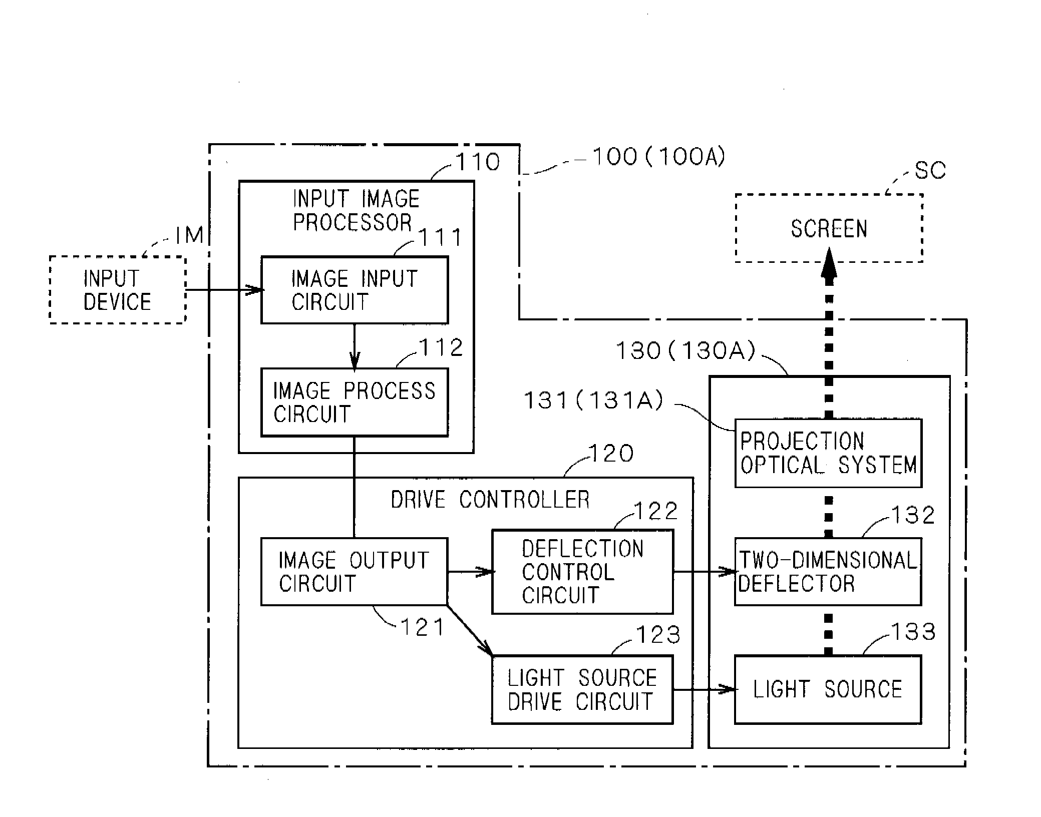
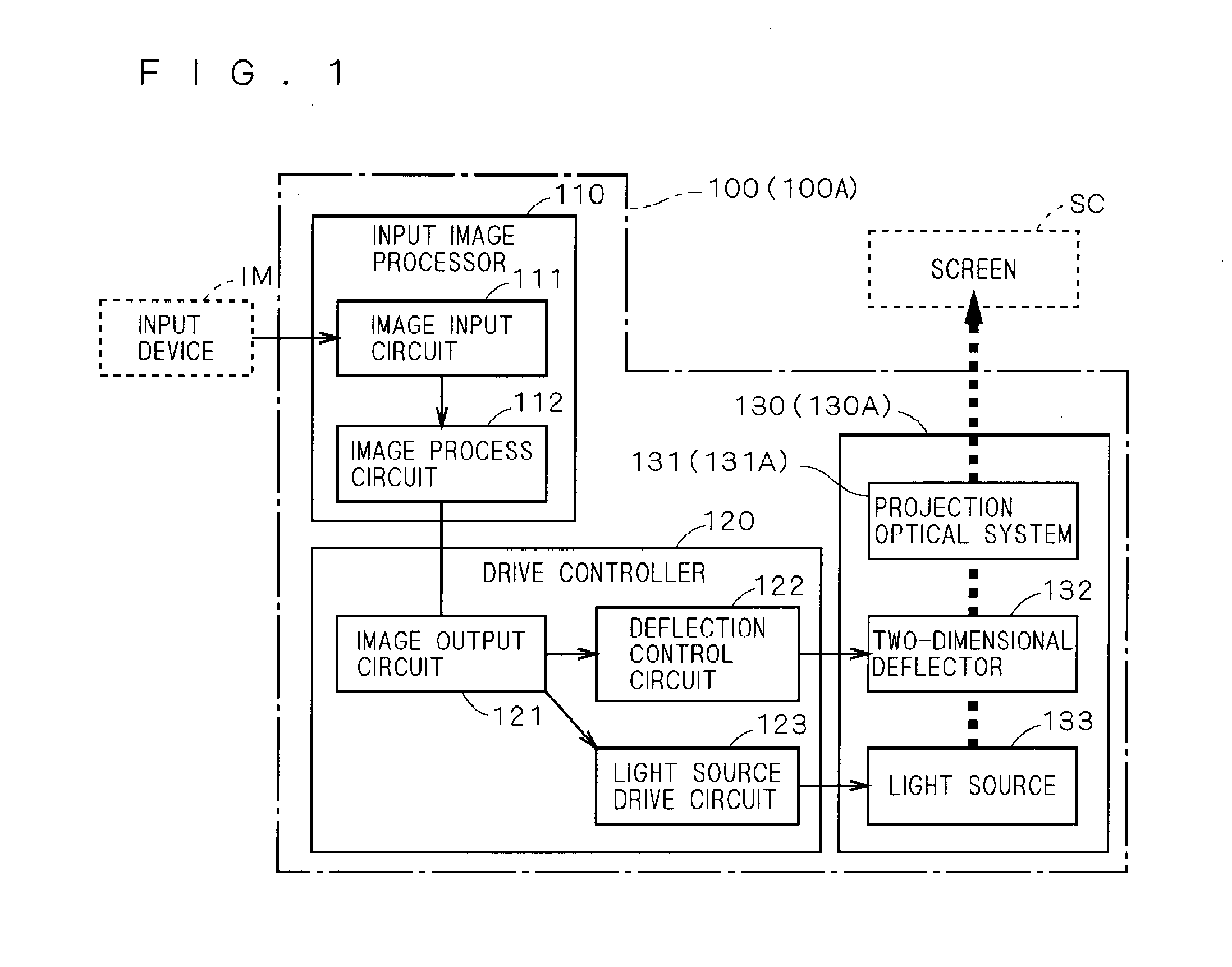
[0077]FIG. 1 is a block diagram showing a functional configuration of an image projector 100 according to a first embodiment of the present invention.

[0078]The image projector 100 is an apparatus for projecting a dynamic image onto a screen SC as a projection plane and mainly has an input image processor 110, a drive controller 120, and an optical mechanism 130.

[0079]The input image processor 110 has an image input circuit 111 and an image process circuit 112.

[0080]The image input circuit 111 receives an image signal input from an input device IM and outputs it to the image process circuit 112. The image process circuit 112 properly performs image process on the image signal from the image input circuit 111 and outputs the processed image signal to the drive controller 120.

[0081]An example of the input device IM is a personal computer, and an example of the image signal is a general NTSC signal. Examples of the image process in the im...

second embodiment

[0200]In the image projector 100 of the first embodiment, each time a laser beam is reflected, a light ray is split in the +y direction, and the deflection scan drive correction is employed as a method of correcting distortion in the horizontal scan direction. In contrast, in an image projector 100A in the second embodiment, the method of separating a light ray is different from that of the image projector 100 of the first embodiment, and optical correction is employed as a method of correcting distortion in the horizontal scan direction.

[0201]The image projector 100A of the second embodiment will be described below. The functional configuration of the image projector 100A of the second embodiment is similar to that of the image projector 100 of the first embodiment. The same reference numerals are designated to similar parts and the description will not be repeated. Different parts will be mainly described.

[0202]Configuration of Optical Mechanism

[0203]In the image projector 100A of...


PUM


Abstract

An object of the present invention is to provide an image projector capable of projecting a high-quality image while realizing small size. In the image projector, a light flux is deflected two-dimensionally by turning a reflector for reflecting a light flux emitted from a light source around a second axis almost orthogonal to a first axis as a center by resonant drive while turning the reflector around the first axis as a center by non-resonant drive. Shape of one or more optical surfaces of a projection optical system for projecting an image onto a projection plane by guiding light onto the projection plane includes a shape for performing a correction for maintaining scanning speed of the light flux along one scan direction on the projection plane almost constant and a shape for performing a correction for suppressing a distortion in an image along the other scan direction almost orthogonal to the one scan direction on the projection plane. By controlling turn of the reflector, at least one of a correction for maintaining scanning speed of the light flux along the other scan direction on the projection plane almost constant and a correction for suppressing a distortion in an image along the one scan direction on the projection plane is performed.

Description

[0001]This application is based on application No. 2007-087702 filed in Japan, the contents of which are hereby incorporated by reference.BACKGROUND OF THE INVENTION[0002]1. Field of the Invention[0003]The present invention relates to an image projector for projecting an image to a projection plane. More particularly, the invention relates to, especially, an optical system of a small-sized image projector for projecting an image by two-dimensionally deflecting and scanning light. More specifically, the invention relates to a so-called optical engine part of a small size in, for example, a pocket projector, a data projector, a rear projection television, or the like.[0004]2. Description of the Background Art[0005]Various small-sized image projectors for two-dimensionally deflecting and scanning light from a light source and projecting an image are proposed (for example, Japanese Patent Application Laid-Open No. 2006-178346 and SID 06 DIGEST, pp. 2015-2017, 73.3). As means for two-dim...

Claims


Application Information

Patent Timeline
Patent Type & Authority Applications(United States)
IPC IPC(8): G03B21/28
CPCG02B17/0621G02B26/105G02B27/0025G03B21/28H04N9/3129H04N9/3164H04N9/3185Y10S359/904F21S41/675
Inventor KONNO, KENJIMIZUMOTO, KENJI
Owner KONICA MINOLTA OPTO
Why Eureka
Try Eureka