
Lamp unit of vehicular headlamp

a headlamp and lamp unit technology, applied in the direction of transportation and packaging, semiconductor devices for light sources, lighting and heating apparatus, etc., can solve the problem of extreme difficulty in using a part of the direct light from the led to illuminate the overhead zone with a structure, and achieve the effect of reducing the amount of light toward the essential light distribution portion of the headlamp

Inactive Publication Date: 2008-10-02
KOITO MFG CO LTD
View PDF2 Cites 29 Cited by
  • Summary
  • Abstract
  • Description
  • Claims
  • Application Information

AI Technical Summary

Benefits of technology

[0012]One or more embodiments of the prevent invention enable light distribution above a cut-off line using a currently available LED as a light source, without reducing an amount of light toward an essential portion of headlamp light distribution.
[0014]According to the lamp unit of the vehicular headlamp of one or more embodiments of the present invention, it is possible to distribute the minimum required amount of light radiated from the light source above a cut-off line while using a semiconductor light-emitting element such as a currently available LED as the light source. Furthermore, it is possible to minimize a decrease in the amount of light to an essential light distribution portion of the headlamp.
[0016]According to the lamp unit of the vehicular headlamp of one or more embodiments of the present invention, it is possible to distribute the minimum required amount of light radiated light from the light source above a cut-off line while using a semiconductor light-emitting element such as a currently available LED as the light source. Furthermore, it is possible to minimize a decrease in the amount of light to an essential light distribution portion of the headlamp.
[0017]According to one or more embodiments of the present invention, the shade is formed from a transparent material, the second reflector is formed by a surface treatment such as metal vapor deposition, the light transparent portion is formed without being subjected to the surface treatment. In addition, the light passing through the light transparent portion refracts when incident to the transparent material, proceeds to inside the transparent material, radiates from a light radiation portion formed near the rearward focal point of the projection lens, and is incident to the projection lens. Therefore, it is possible to precisely control a light radiation position for upward light distribution, thus enabling precise control of a position for upward light distribution.
[0018]According to one or more embodiments of the present invention, the light radiation portion is positioned downward and rearward from the rearward focal point of the projection lens. Therefore, it is possible to suitably diffuse light for upward light distribution, thus preventing more brightness than necessary from being produced.

Problems solved by technology

However, according to the lamp unit of the vehicular headlamp disclosed in Patent Document 2, given current LED technology, in view of the narrow light-emitting area of the LED, it is extremely difficult to use part of the direct light from the LED to illuminate the overhead zone with a structure as shown in FIG. 10 of Patent Document 2.

Method used


Image

  • Lamp unit of vehicular headlamp
  • Lamp unit of vehicular headlamp
  • Lamp unit of vehicular headlamp

Examples


Embodiment Construction

[0026]Hereinafter, embodiments of a lamp unit of a vehicular headlamp according to the present invention will be described with reference to the accompanying drawings. Note that embodiments shown in the drawings apply the present invention to a lamp unit of an automotive headlamp.

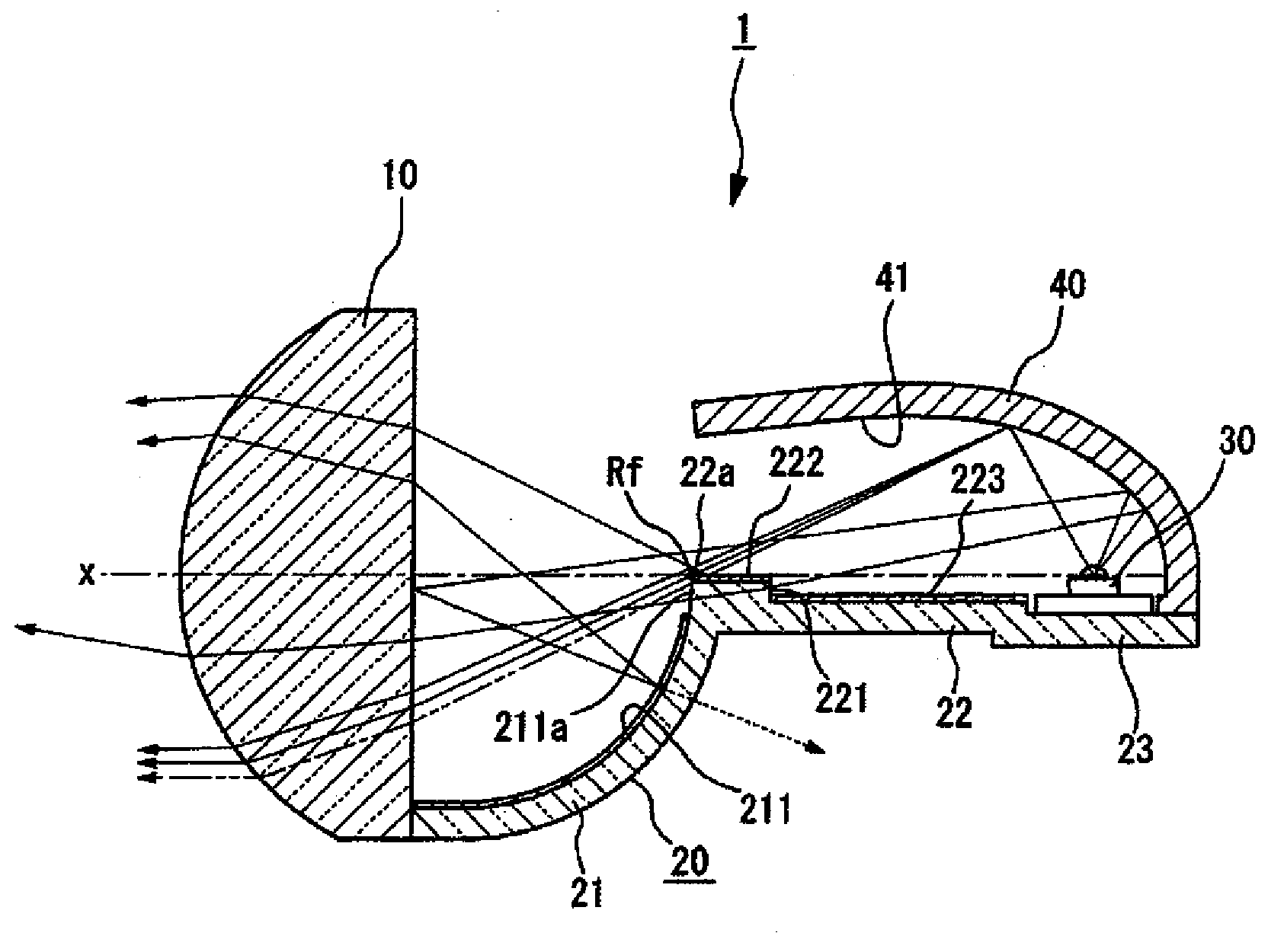
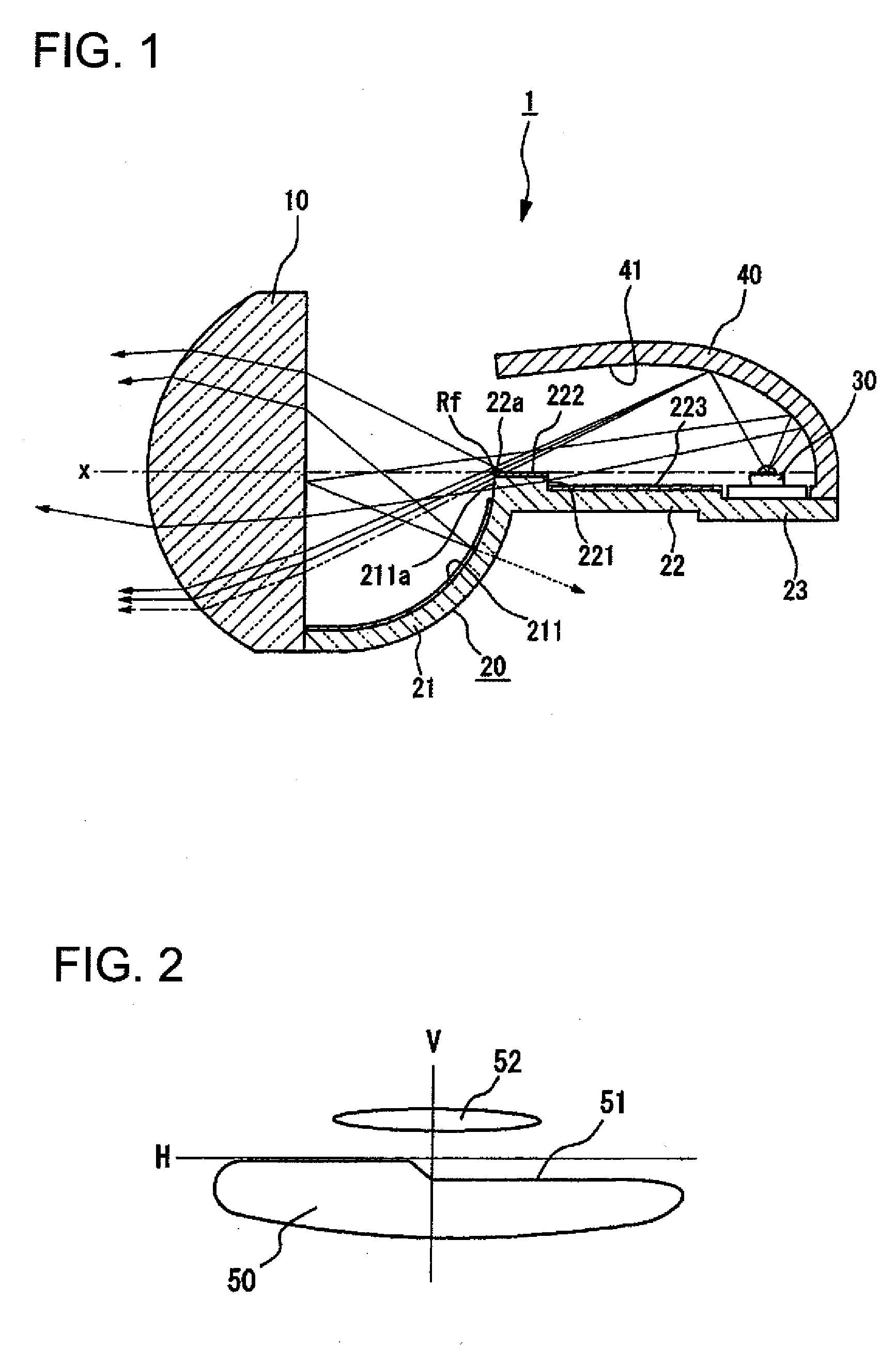
[0027]FIG. 1 shows a first embodiment of the lamp unit of the vehicular headlamp according to the present invention.

[0028]A lamp unit 1 of the automotive headlamp includes a projection lens 10 with an optical axis x. The projection lens 10 is supported by a front end portion of a supporting portion 21 that forms part of a base member 20. The base member 20 is formed integrated with the supporting portion 21, a shade portion 22, and a light source installation portion 23. The respective portions of the base member 20 are integrally formed from a transparent material such as transparent synthetic resin.

[0029]The shade portion 22 is formed as a plate-shaped portion generally along the optical axis of the proje...


PUM


Abstract

A lamp unit of a vehicular headlamp includes a projection lens with an optical axis; a light source formed from a semiconductor light-emitting element; a first reflector that reflects light from the light source so as to condense such light on or near the optical axis; and a shade positioned between the light source and the projection lens so as to extend along the optical axis direction. The shade shields part of the light reflected by the first reflector. In the lamp unit of the vehicular headlamp, a shielding surface extends rearward from a front end of the shade, where the shade is positioned near a rearward focal point Rf of the projection lens. The shielding surfaces serve as a second reflector that reflects light from the first reflector toward the projection lens. In addition, a transparent portion is formed on part of the second reflector such that part of the light reflected by the first reflector passes downward of the rearward focal point of the projection lens and is then incident to the projection lens.

Description

BACKGROUND OF INVENTION[0001]1. Field of the Invention[0002]The present invention relates to a novel lamp unit of a vehicular headlamp. More specifically, the present invention relates to radiating light for viewing an overhead sign above a road (referred to as an overhead sign below) using part of headlamp light.[0003]2. Related Art[0004]A low-beam of a headlamp of a vehicle such as an automobile is strongly suppressed such that upward diffusion light is not generated, in order to ensure that dazzling light is not radiated to drivers of preceding vehicles, pedestrians, and the like. Therefore, little light reaches an upper side of a cut-off line limiting an upper end edge.[0005]Meanwhile, in current transportation conditions, overhead signs are used to display a branch direction of a road, a distance to a major location, and the like. The overhead signs are formed from a highly reflective material to improve visibility. However, a low-beam with good performance radiates little ligh...

Claims


Application Information

Patent Timeline
IPC IPC(8): F21V7/00
CPCF21S48/1159F21S48/1241F21S48/1335F21S48/145F21Y2101/02F21Y2115/10F21S41/285F21S41/24F21S41/25F21S41/32F21S41/43F21S41/365F21W2102/18F21S41/148F21S41/323
Inventor NAGANAWA, MASAHITOKOMATSU, MOTOHIRO
Owner KOITO MFG CO LTD
Learn More