

Layer 2 routing protocol
a routing protocol and layer 2 technology, applied in the field of wireless communication, can solve the problems of disadvantages of traditional wire-based ip routing protocols, and achieve the effect of reducing the overhead needed to exchange routing messages and increasing performan
- Summary
- Abstract
- Description
- Claims
- Application Information
AI Technical Summary
Benefits of technology
Problems solved by technology
Method used
Image

Examples
Embodiment Construction
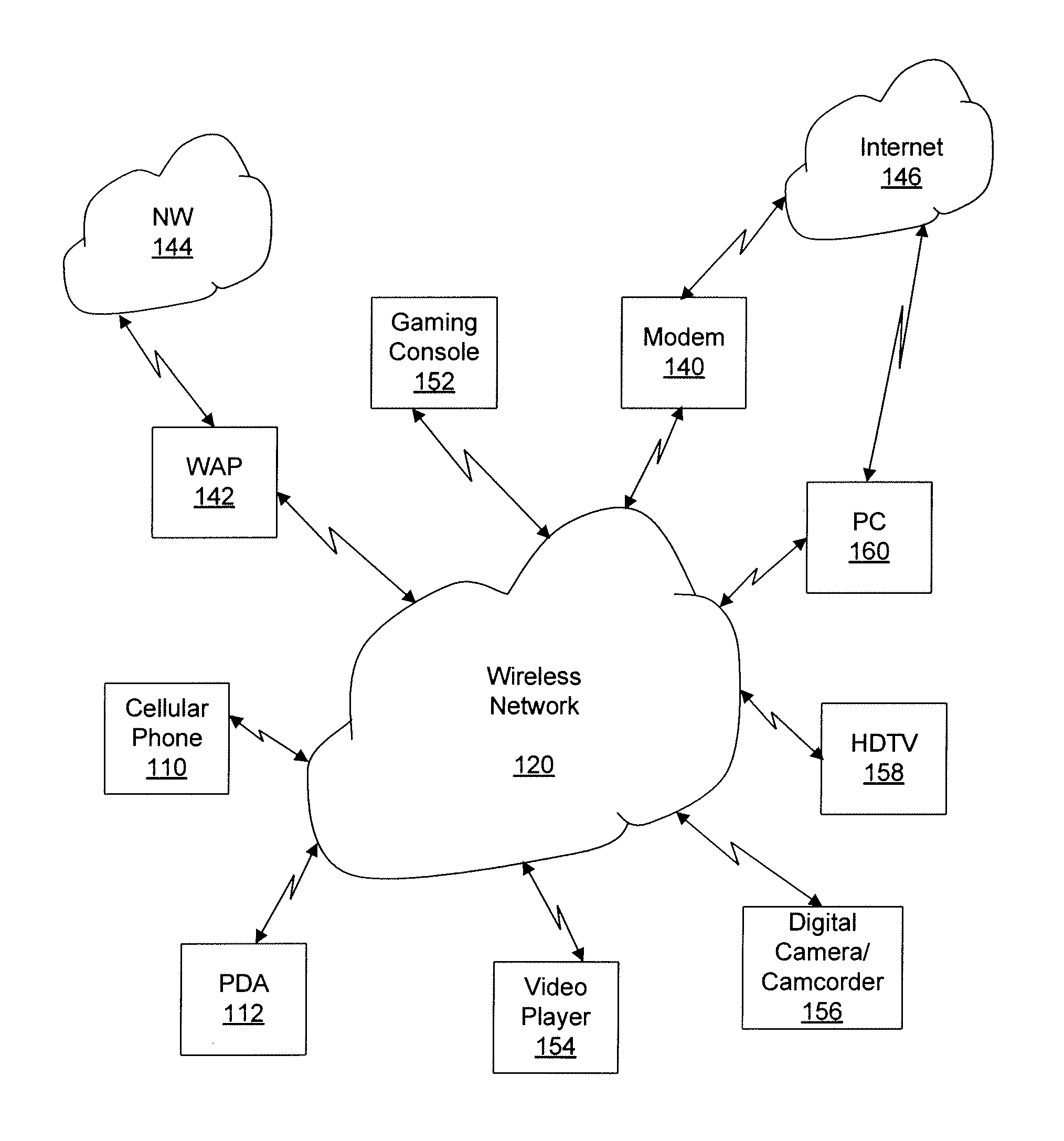
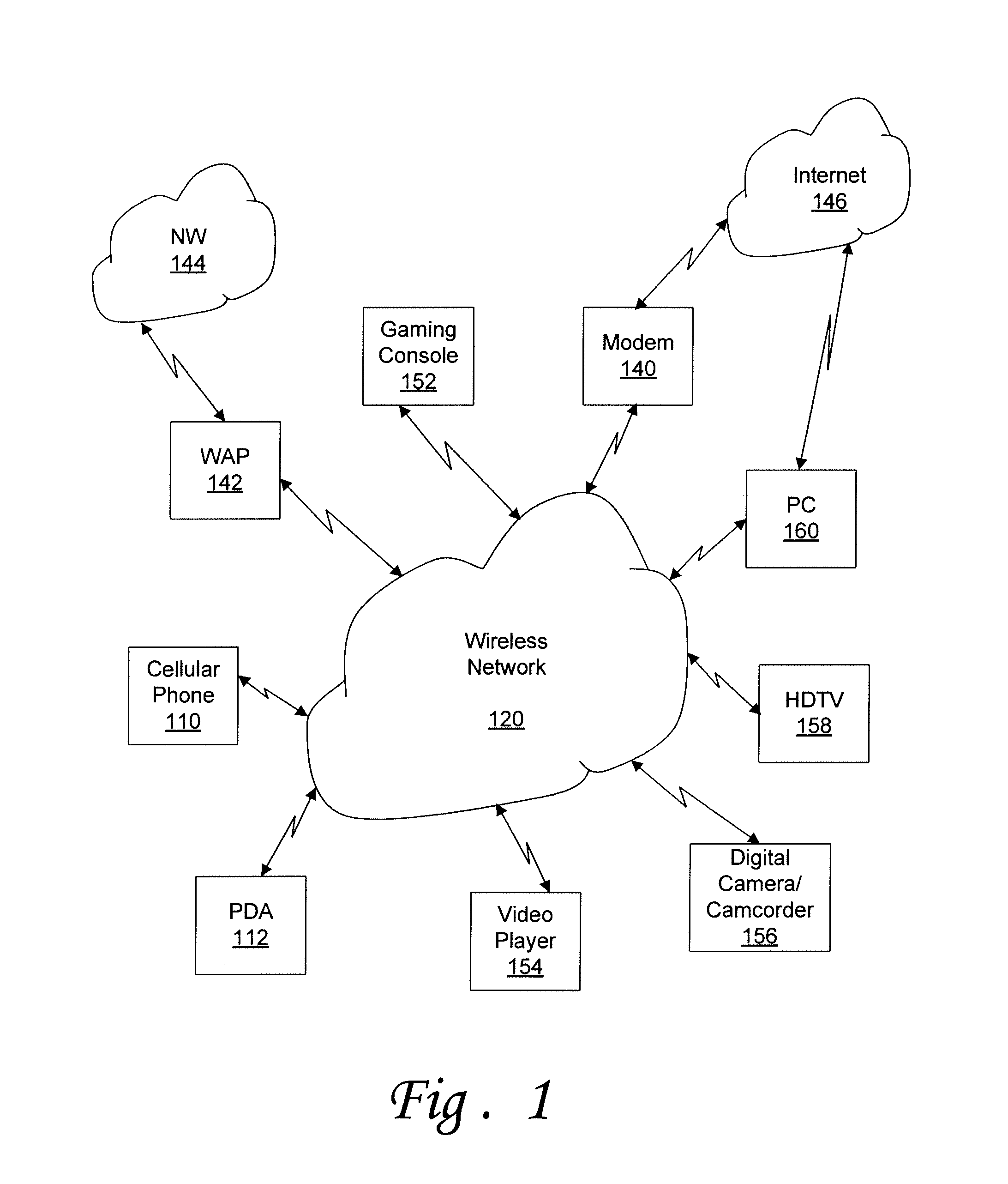
[0009]According to various embodiments of the invention, a routing protocol that operates at layer 2 (i.e., the MAC layer) is proposed. A routing protocol that operates at layer 2 might be transparent to the upper layer (e.g., the IP layer). Accordingly, in some embodiments no modifications to the upper layer are required to enable multi-hop communication for WiMedia-based devices. At layer 3 of a device, devices that are several hops away might appear as “neighbors,” for example, on the same segment, for example, as if they are all on the same Ethernet. Additionally, because the solution operates at layer 2, the proposed scheme, in various embodiments, might take advantage of information and tools such as detailed channel condition and beacon protocol that may be available at layer 2. This might be done to reduce the overhead needed to exchange routing messages or to choose routes that might offer increased performance under certain circumstances.
[0010]Bridges or routers might be u...
PUM
 Abstract
Description
Claims
Application Information