Method and apparatus for digital subscriber line transfer

a technology of digital subscriber line and transmission method, applied in the direction of electrical apparatus, digital transmission, signal channel, etc., can solve the problems of preventing the use of vdsl technology, and achieve the effect of reducing costs and complexities, and reducing uplink capacity

Inactive Publication Date: 2008-10-02
WIRELESS LAN SYST
View PDF1 Cites 1 Cited by
  • Summary
  • Abstract
  • Description
  • Claims
  • Application Information

AI Technical Summary

Benefits of technology

[0014]However, the primary problem underlying the invention is not expansion of VDSL coverage, because VDSL coverage could be expanded by DMT technology. Rather the primary problem is elimination of the costs and complexities incurred by DMT technology. Further reduction of costs and complexities can be obtained by suitable filter construction. A VDSL transceiver unit comprises a digital part and an analogue part. The analogue part comprises filters that in conventional VDSL transceiver units are high-pass and low-pass filters. According to of a preferred embodiment of the invention, the first standardized VDSL downlink band D1 is implemented by a bandpass filter for downlink transfer and as a bandstop filter for uplink transfer.
[0015]Alternatively, a transceiver unit may use both the standardized uplink band U1, or bands U1 and U2 as the case may be, and the non-VDSL uplink band according to the invention, for higher uplink capacity.
[0016]According to another preferred embodiment of the invention, the transceiver unit is able to negotiate with its peer entity to learn what frequency bands are usable. Conventional POTS (“plain old telephone system”) modems use negotiation because a modem does not know what kind of a modem it is communicating with. VDSL transceiver units are different, however, because a subscriber's transceiver unit always communicates via the same network element that comprises its peer entity. Accordingly, a negotiation over the available frequency bands seems like an added complexity and a waste of time. On closer look a negotiation phase may prove useful, however, because situations may change, and added flexibility is welcome.

Problems solved by technology

These limitations practically prevent the use of VDSL technology if the standardized VDSL uplink frequency band from approximately 3 MHz to approximately 5 MHz is unavailable for uplink transfer.

Method used


Image

  • Method and apparatus for digital subscriber line transfer
  • Method and apparatus for digital subscriber line transfer
  • Method and apparatus for digital subscriber line transfer

Examples


Embodiment Construction

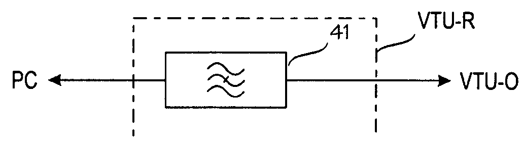
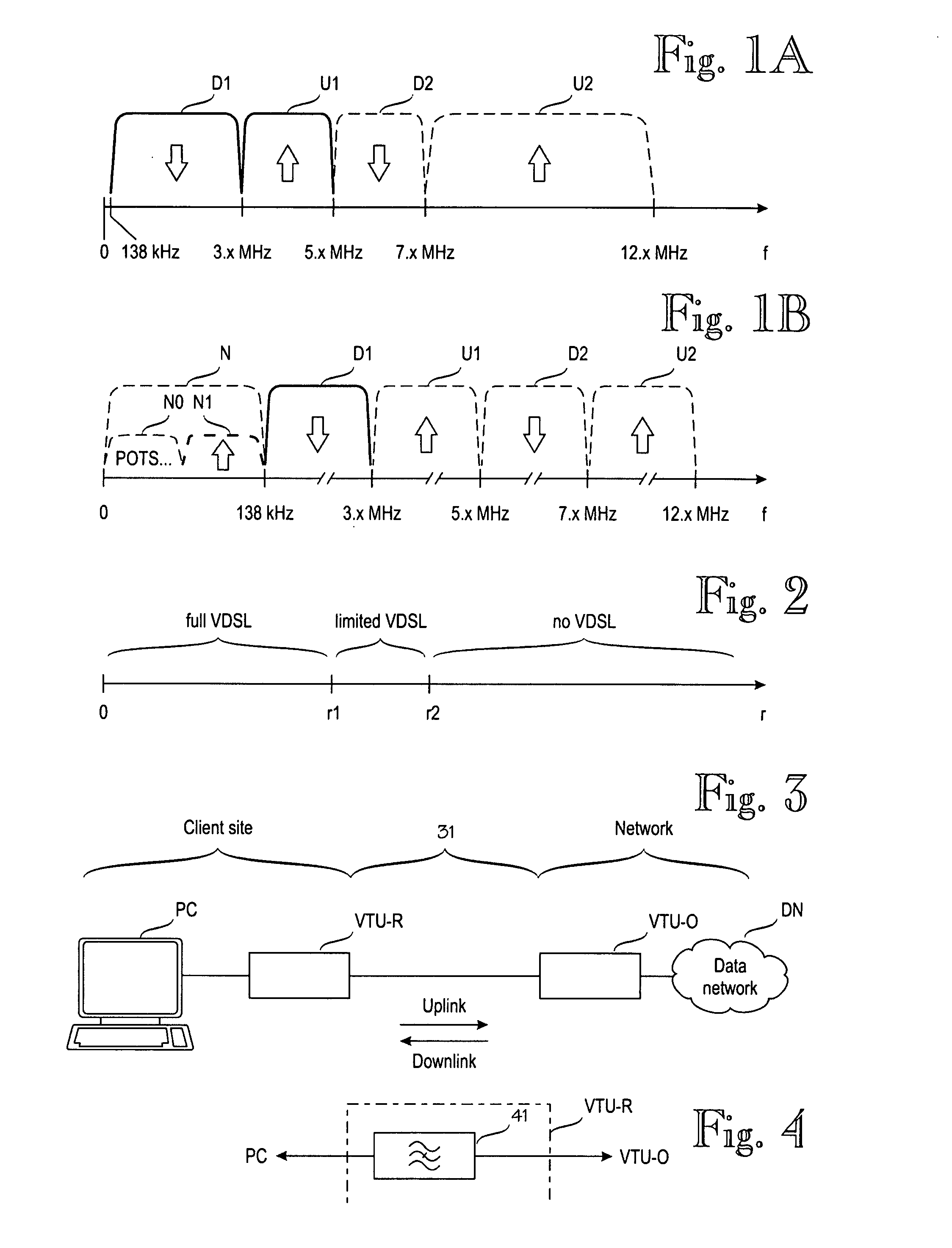
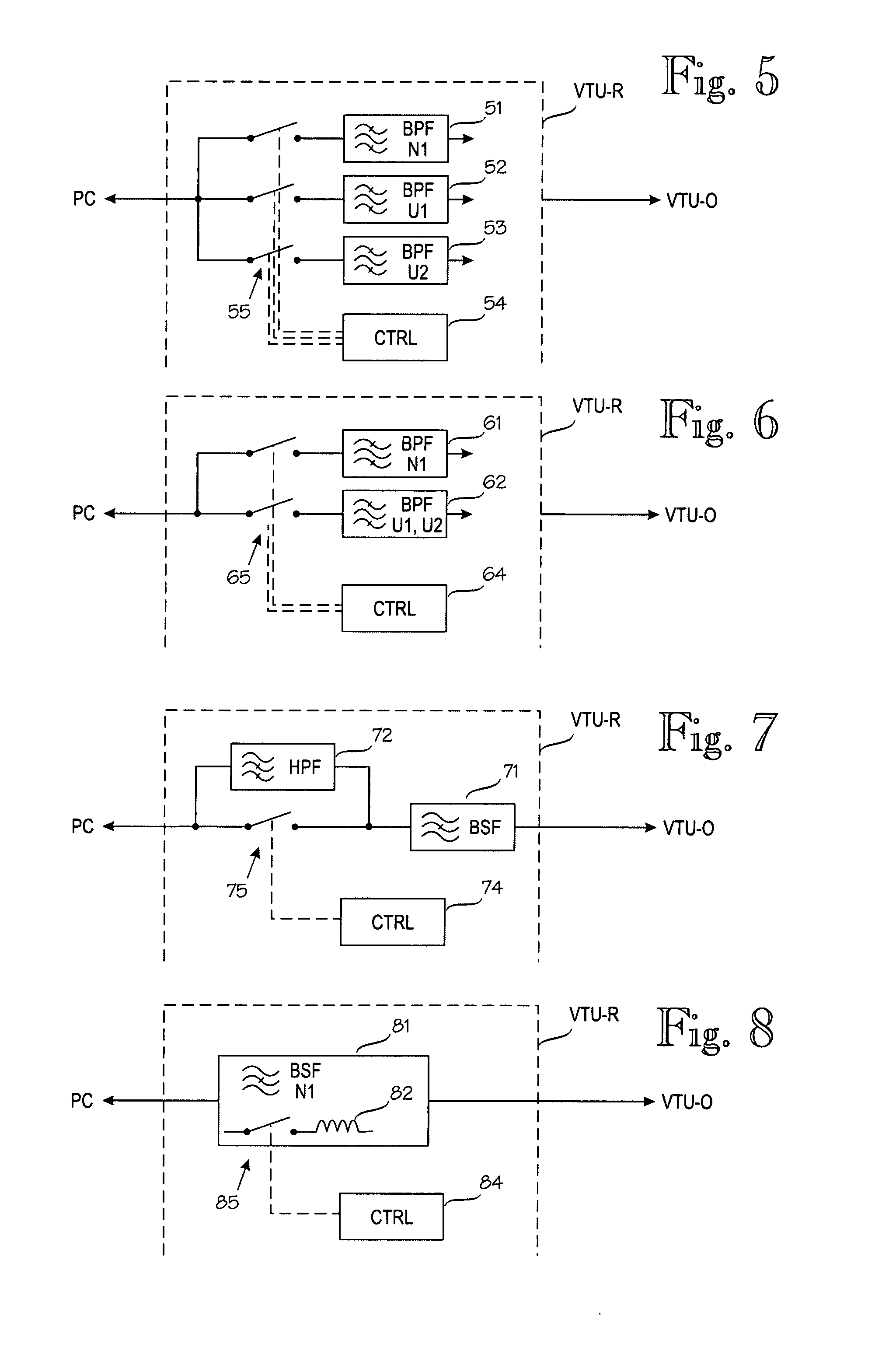
[0023]FIG. 1B illustrates the frequency bands used by a transceiver unit according to the invention. Note that in FIG. 1A the frequency axis f was drawn to scale, whereas in FIG. 1B, the lower end of the frequency spectrum is very much exaggerated. In FIG. 1 B, reference sign N denotes a frequency band allocated to non-VDSL use by current VDSL standards. For example, the non-VDSL band N comprises frequencies used by conventional telephony, or POTS, signals. These frequencies are denoted by reference sign N0. According to the invention, a transceiver unit is capable of using a part of the non-VDSL band N for uplink use, at least in a situation where no other uplink bands are usable. In FIG. 1B, such an uplink band that is currently allocated to non-VDSL use is denoted by reference sign N1. Again, bold outlines show frequency bands that are actually available. In the situation illustrated by FIG. 1B, none of the standardized VDSL uplink bands U1 or U2 are available. The non-VDSL uplin...


PUM


Abstract

VDSL (Very-high-data-rate Digital Subscriber Line) technology uses at least one downlink frequency band (D1, D2) for conveying information from a data network to a subscriber's transceiver unit. At some sites VDSL technology cannot be used because no standardized uplink frequency band (U1, U2) is usable. The invention solves this problem by using at least one non-VDSL uplink frequency band (N1) for conveying information from the subscriber's transceiver unit to the data network.

Description

CROSS REFERENCE TO RELATED APPLICATIONS[0001]This application is a continuation of U.S. patent application Ser. No. 09 / 975,548, filed Oct. 12, 2001, the entire contents of which is incorporated herein by reference.BACKGROUND OF THE INVENTION[0002]The invention relates to DSL (Digital Subscriber Line) technology, and more particularly, to a transceiver unit using DSL technology. DSL refers generally to a public network technology that delivers relatively high bandwidth over conventional telephone copper wiring at limited distances. A transceiver unit is the interface point between a data processing apparatus (such as a user's computer or the corresponding device in a switch or exchange) and a data network. DSL transceiver units may also be called DSL modems, but the term modem is somewhat misleading and is later restricted to telephony usage. A description of DSL technology and examples of DSL equipment can be found in U.S. Pat. No. 6,226,322 to Subahashish Mukherjee.[0003]As stated ...

Claims


Application Information

Patent Timeline
Patent Type & Authority Applications(United States)
IPC IPC(8): H04J1/00H04L5/02H04L5/14
CPCH04L5/023H04L5/143
Inventor SUONSIVU, HEIKKIETELANIEMI, VELISIPILA, JURI
Owner WIRELESS LAN SYST
Why Eureka
Try Eureka