Focus State Detection Apparatus and Optical Instrument

Inactive Publication Date: 2008-10-02
CANON KK
View PDF5 Cites 10 Cited by
  • Summary
  • Abstract
  • Description
  • Claims
  • Application Information

AI Technical Summary

Benefits of technology

[0007]It is an object of the present invention to realize a focus detection technique in which even if it is necessary to detect a defocus state upon e

Problems solved by technology

If, however, focus detection cannot be performed, the accumulation control areas must be changed, and accumulation operation and calculation operation must be done again.
This prolongs the time required for focus detection.
If, however, accumulati

Method used


Image

  • Focus State Detection Apparatus and Optical Instrument
  • Focus State Detection Apparatus and Optical Instrument
  • Focus State Detection Apparatus and Optical Instrument

Examples


Example

First Embodiment

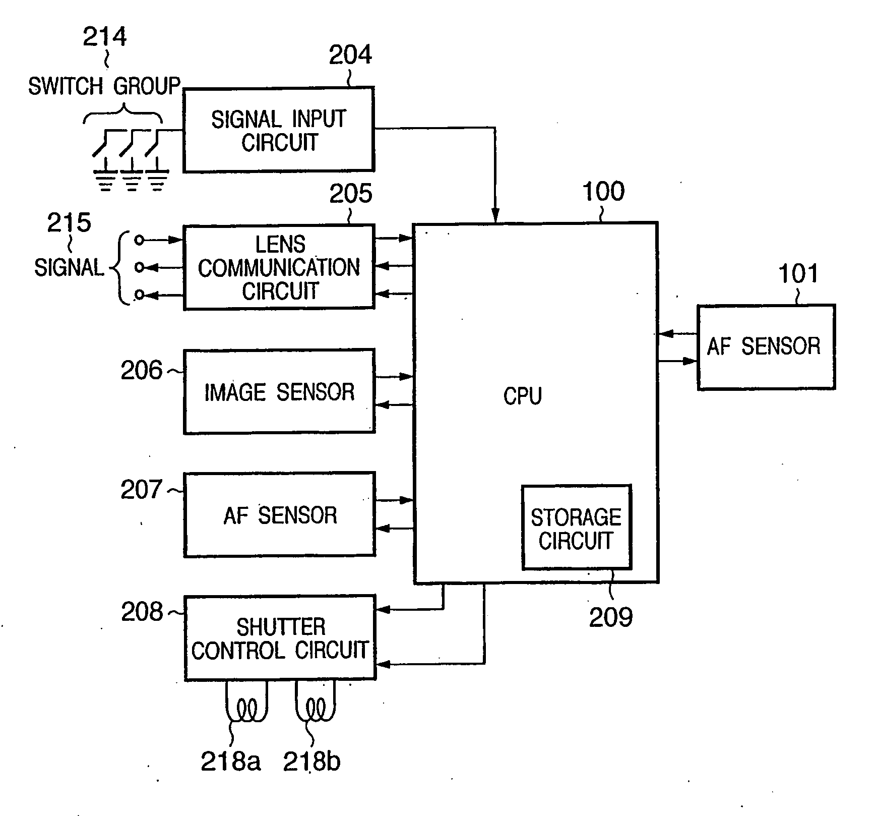
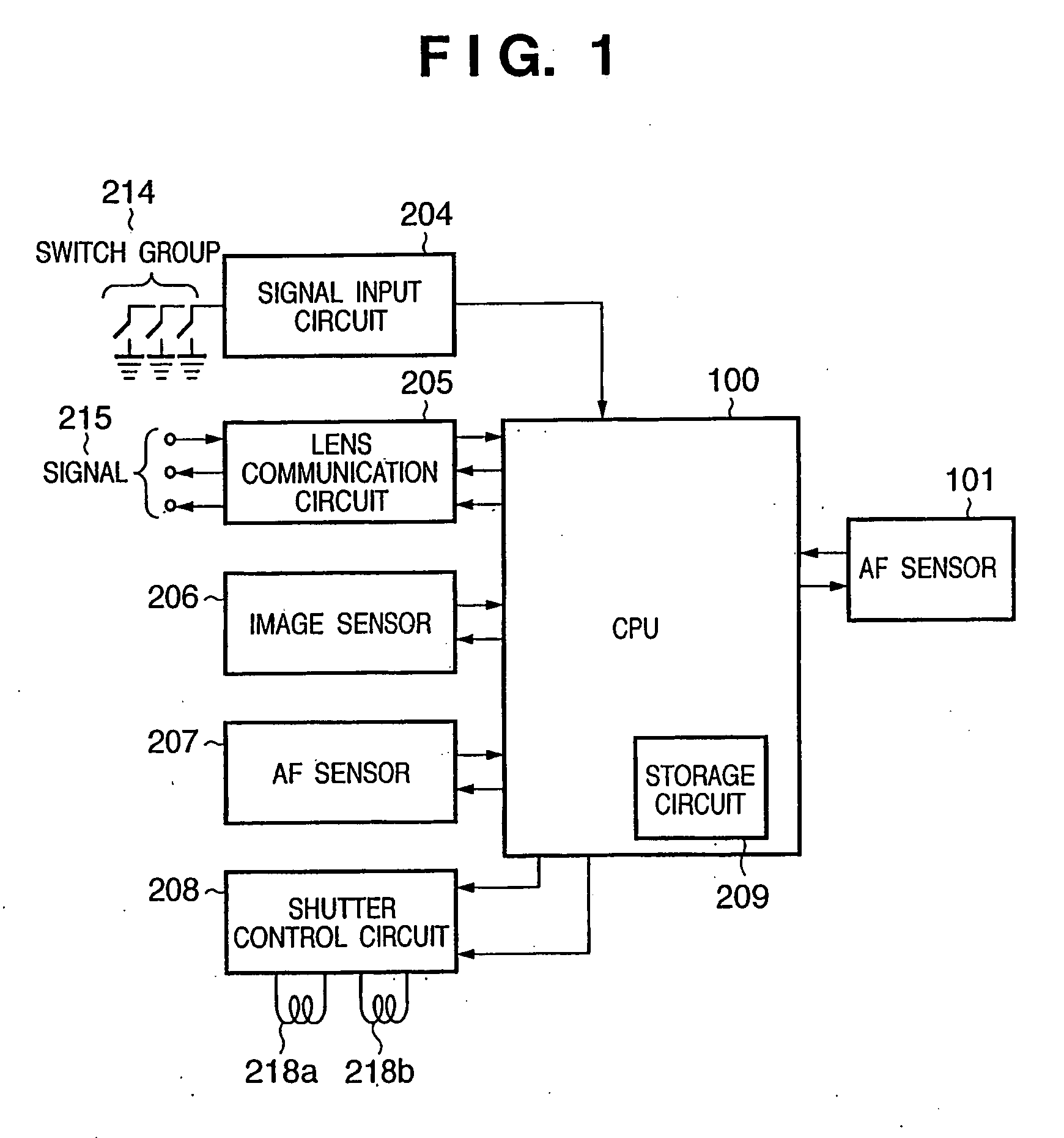
[0050]FIG. 1 is a block diagram showing the circuit arrangement of a camera according to the first embodiment of the present invention. Referring to FIG. 1, a signal input circuit 204 for detecting a switch group 214 for various kinds of operations of the camera, an image sensor 206, an AF sensor 207, a shutter control circuit 208 for controlling shutter magnets 218a and 218b, and an AF sensor 101 are connected to a camera microcomputer (to be referred to as a CPU hereinafter) 100. The CPU 100 transmits a signal 215 to a photographing lens (to be described later) through a lens communication circuit 205 to perform control for a focus position and a stop. The operation of the camera is determined by the setting of the switch group 214.

[0051]The AF sensor 101 comprises a pair of line sensors. The CPU 100 controls the AF sensor 101 to detect a defocus amount from the contrast distribution of an object to be photographed which is obtained by the line sensors, thereby con...

Example

Second Embodiment

[0087]In the focus detection apparatus according to the first embodiment described above, when the area C is enlarged, the areas L and R become narrow. As a result, the detection range of defocus amounts becomes narrow. A technique for solving this problem will be described below as the second embodiment of the present invention.

[0088]FIG. 13 is a block diagram showing the arrangement of a camera according to the second embodiment of the present invention. The same reference numerals as in FIG. 1 denote the same parts in FIG. 13.

[0089]An AF sensor 401 comprises two pairs of line sensors. A CPU 100 incorporates a timer 400 for measuring the accumulation time in the AF sensor 401. Other arrangements are the same as those shown in FIG. 1, and hence a description thereof will be omitted.

[0090]The relationship between the line sensors on the AF sensor 401 and distance measurement points in a photographing frame will be described with reference to FIGS. 14 and 15.

[0091]FI...

Example

Third Embodiment

[0112]The third embodiment of the present invention will be described next. FIG. 19 is a view showing a distance measurement principle using a focus detection apparatus according to the third embodiment of the present invention.

[0113]In the third embodiment, a photographing lens 603 is placed in front of a distance measurement unit 610. The focus state can be changed by changing the position of the photographing lens 603 between an object 601 to be photographed and the distance measurement unit 610, and more specifically, moving the photographing lens 603 in the vertical direction in FIG. 19 (the direction indicated by the arrow in FIG. 19). In the case shown in FIG. 19, a one-bar chart plate (a chart plate with one bar) is used as the object 601.

[0114]The distance measurement unit 610 is provided with a field lens 611, a stop 612, a secondary imaging spectacle lens 613 having two lenses combined, and a light-receiving sensor 614. Unnecessary light beams of light bea...


PUM


Abstract

This invention includes accumulation units (102a, 102b) which accumulate signals obtained by sensing units (111a, 111b), an area determination unit (103, 100) which sets the size of an area of a sensing unit to be segmented into a plurality of areas on the basis of the information of a lens to be focus-detected, accumulation control units (104a-104c, 105) which control, for each of the areas, accumulation of signals obtained in a plurality of areas by the accumulation units, and a defocus detection unit (100) which detects defocus states in the respective areas from accumulated signals from a plurality of areas.

Description

TECHNICAL FIELD[0001]The present invention relates to a focus detection apparatus and focus detection method which detect distance measurement positions.BACKGROUND ART[0002]Conventionally, as a focus detection apparatus for a camera, a focus detection apparatus based on a so-called phase difference detection scheme is known (Japanese Patent Laid-Open No. 09-054242), which detects the defocus amount of an object to be photographed by forming light beams from the object, which have passed through different exit pupil areas of a photographing lens, into images on a pair of line sensors and obtaining the amount of displacement between the relative positions of a pair of object images obtained by photoelectrically converting the object images (which operation will be referred to as phase difference calculation hereinafter), and drives the photographing lens on the basis of the defocus amount.[0003]As a focus detection apparatus of this type, a multifocus detection apparatus is known (Jap...

Claims


Application Information

Patent Timeline
IPC IPC(8): G03B13/18G03B13/32
CPCG02B7/34G03B13/36
Inventor ICHIMIYA, TAKASHIOHTSUKA, MASANORI
Owner CANON KK
Why Eureka
Try Eureka