
Non-marring shaft collar

a shaft collar and non-marring technology, applied in the direction of rod connections, pipes, fastening means, etc., can solve the problems of increased maintenance costs, cost and inconvenience, and the known shaft collar has proved to be unreliable during high-torque operation, so as to increase the gripping ability

Inactive Publication Date: 2008-10-02
DESIGNATRONICS
View PDF14 Cites 10 Cited by
  • Summary
  • Abstract
  • Description
  • Claims
  • Application Information

AI Technical Summary

Benefits of technology

[0008]Consequently, with the deficiencies of known shaft collars clearly in mind, the present invention pertains to an inexpensive, yet reliable, shaft collar, with increased gripping ability, that does not burr, mar, gouge, or otherwise harm or degrade, the surface of the shaft to which the collar is clamped. The increased gripping ability is sufficient to avoid relative motion between the collar and the shaft, even under high torque conditions.
[0011]The narrow arcuate segment of resilient material is bowed or flexed radially inwardly, within its elastic limit. The resilient material may be flexed several times, thus insuring a long operational life, and successful operation, over an extended period of time, for the shaft collar.

Problems solved by technology

Such known shaft collars, however, have caused burrs or marring, of the shaft, so that the shaft can not be used indefinitely, and must be replaced, periodically, leading to increased maintenance costs, delays or failures in system operation.
Additionally, known shaft collars have proven to be unreliable during high torque operations, for the tips of the set screws gouge the metal shaft, in a point-to-point manner and slip thereabout.
Although the holding strength of the clamps disclosed by Turro and Evans represented an advance over prior shaft collars, and marring of the shaft may be reduced, the cost and inconvenience of properly locating a metallic spring insert within the body of the collar introduced additional cost and complexity into the manufacturing and assembly process.

Method used


Image

  • Non-marring shaft collar
  • Non-marring shaft collar
  • Non-marring shaft collar

Examples


Embodiment Construction

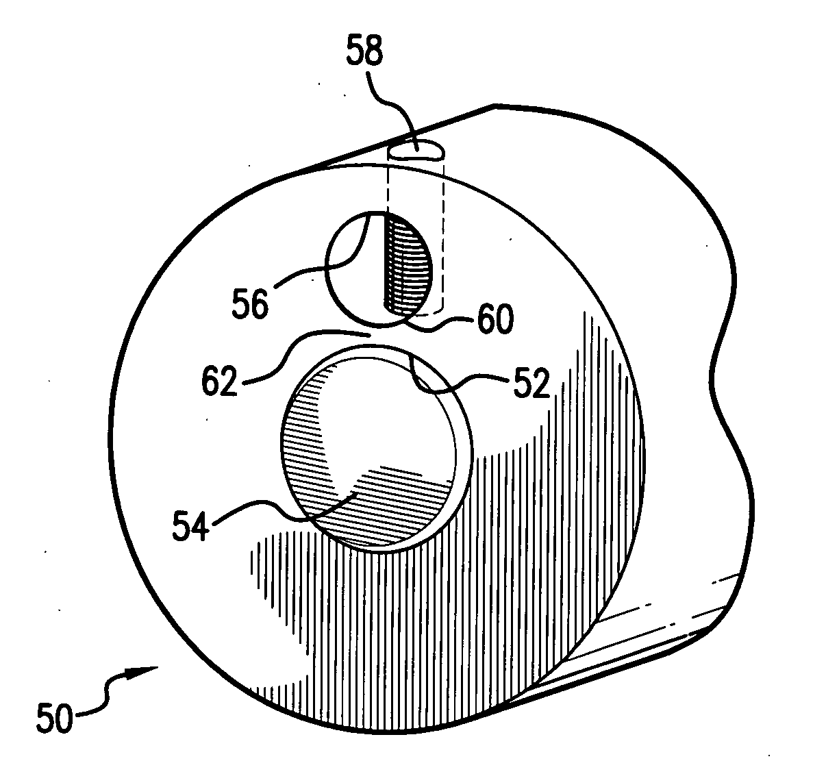
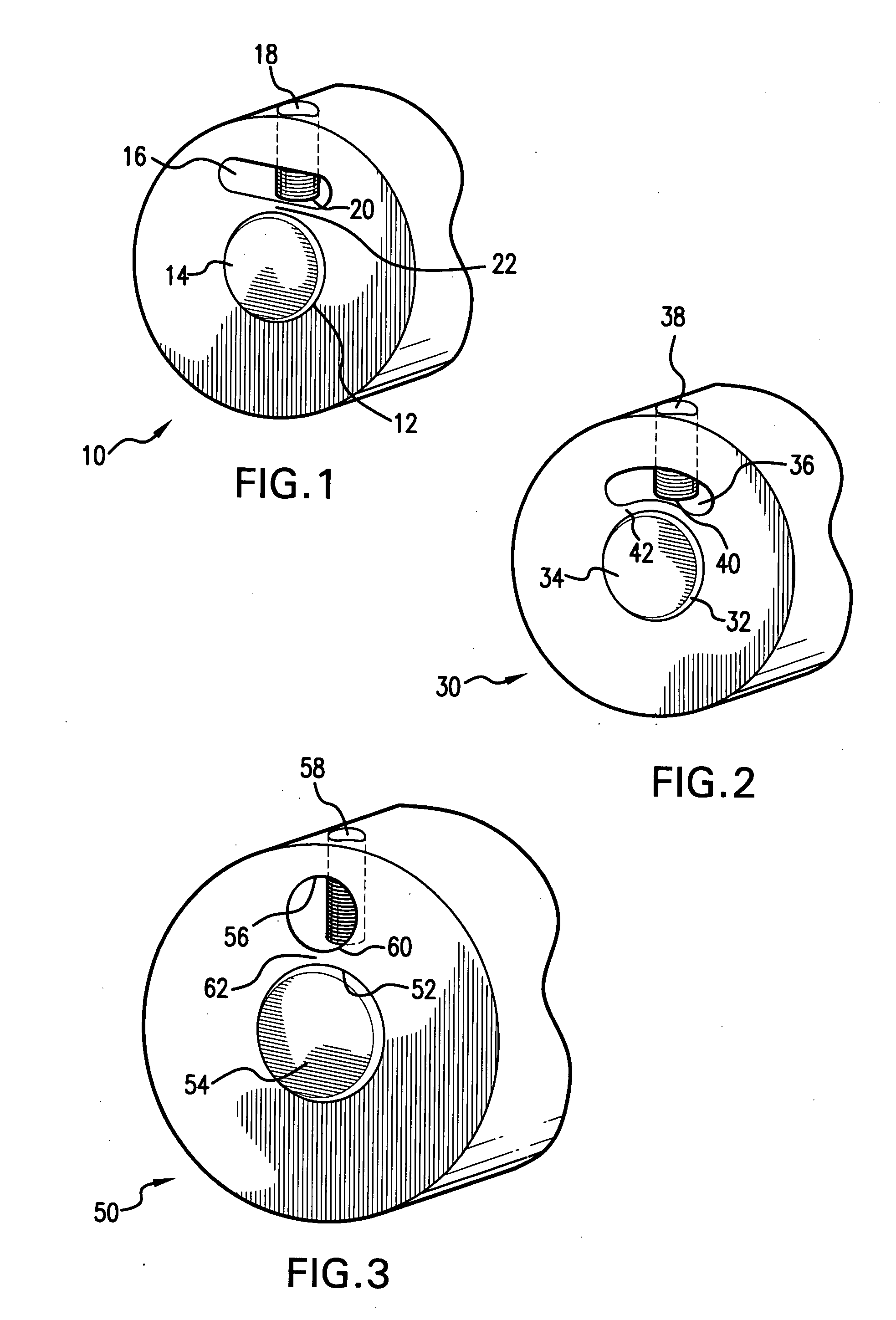
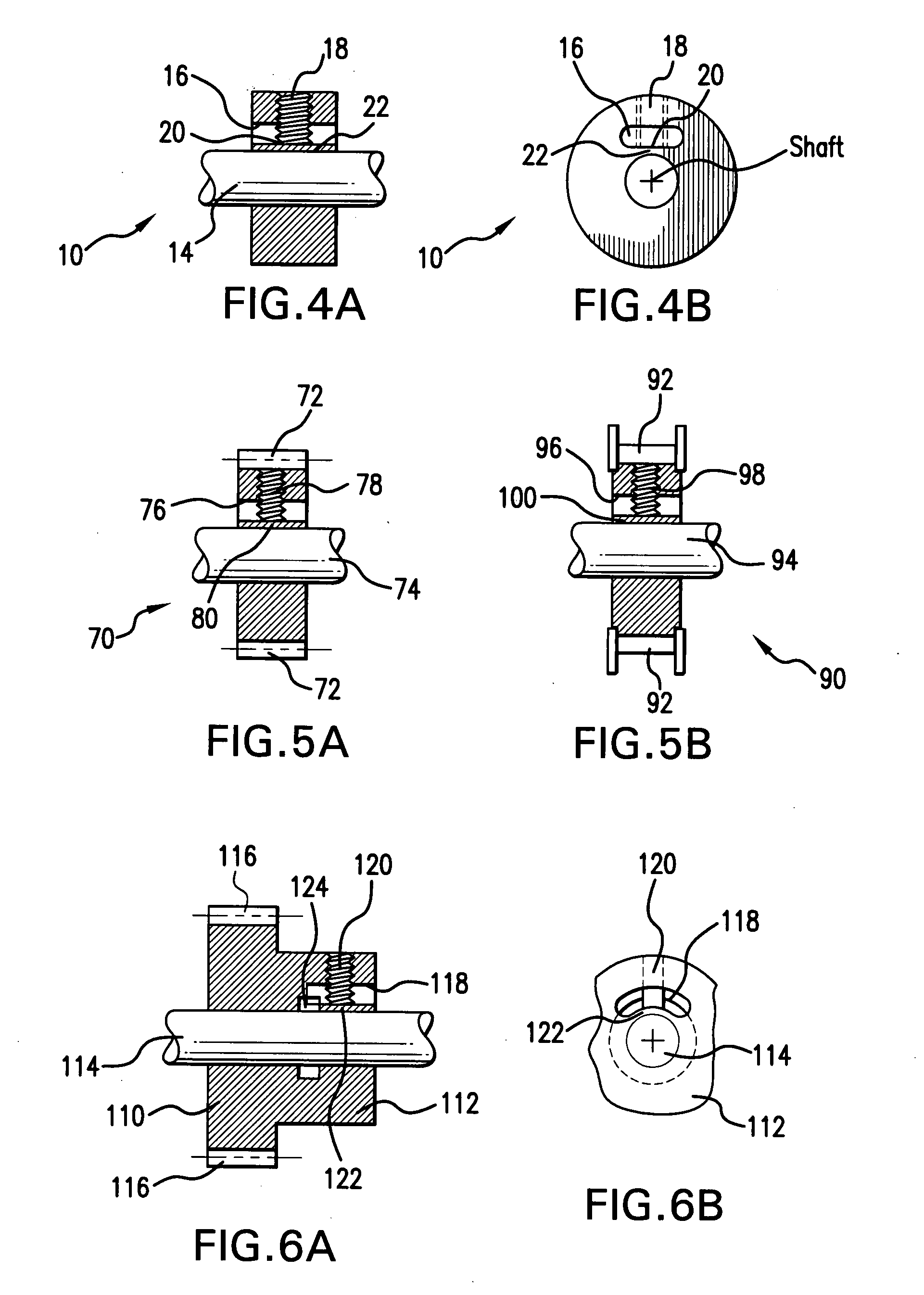
[0027]FIG. 1 depicts the preferred embodiment of applicant's invention comprising a cylindrical collar 10 with a central bore 12 that fits over the exterior diameter of cylindrical shaft 14. A horizontally extending slot 16, of elliptical shape, is formed in the body of collar 10, and set screw 18 is operatively associated with slot 16.

[0028]Set screw 18 is advanced, in the radial direction, through slot 16. The inner tip 20 of set screw 18 contacts the wall defining the base of slot 16, and exerts an inwardly, radially directed force thereupon. The base deflects and presses arcuate segment 22 against the outer diameter of shaft 14 to lock collar 10 in fixed position on the shaft. The collar remains in locked position, until set screw 18 is withdrawn from contact with the base of slot 16. Set screw 18, made of metal, does not contact shaft 14, and arcuate segment 22 is deflected, within its elastic limit, so that the collar may be used repeatedly, without loss of effective holding p...


PUM


Abstract

A shaft collar including a body with a centrally located bore fits over an elongated shaft. An aperture extends laterally across the body in the vicinity of the bore. The aperture extends laterally into the body also, leaving an arcuate segment situated, radially, between the bore and the aperture. A set screw is advanced radially inwardly through the apertures to press against the arcuate segment and deflect same into engagement with the outer diameter of the elongated shaft. The aperture may possess an elliptical cross-section, an arcuate cross-section, or may assume a circular cross-section. The shaft collar can be made from metal or plastic since the tightening process is performed with zero relative motion between the collar and shaft, and therefore there will be no marring or scratching of the shaft.

Description

BACKGROUND OF THE INVENTION[0001]The present invention relates to a shaft collar, and similar mechanical components, that are secured snugly around a shaft in a slip-free manner, without marring the surface of the shaft.[0002]Known shaft collars, and similar mechanical components, such as gears, pulleys, hex nuts, handles, and the like, usually include a cylindrical body with a centrally located bore; the bore fits over the outer diameter, or periphery, of an elongated cylindrical shaft. The shaft collar is secured to the shaft by tightening radially spaced set screws. The inner end or tip of each screw presses against the outer diameter of the shaft, and retains the collar in fixed position upon the shaft.[0003]Such known shaft collars, however, have caused burrs or marring, of the shaft, so that the shaft can not be used indefinitely, and must be replaced, periodically, leading to increased maintenance costs, delays or failures in system operation. Additionally, known shaft collar...

Claims


Application Information

Patent Timeline
IPC IPC(8): F16B7/08
CPCF16B21/00Y10T403/4688F16D1/087F16D1/0847F16B2200/406
Inventor LINDEMANN, ROBERT
Owner DESIGNATRONICS
Learn More