Prefabricated levee apparatus and system

a levee and prefabricated technology, applied in the field of levee apparatus and system, can solve the problems of large land acquisition, significant increase in the cost of the structure, limited current levee design, etc., and achieve the effect of minimizing the footprint, maximum scour, and increasing the footprint of the structur

Inactive Publication Date: 2008-10-02
PHILLIPS AMANDA
View PDF19 Cites 14 Cited by
  • Summary
  • Abstract
  • Description
  • Claims
  • Application Information

AI Technical Summary

Benefits of technology

[0012]An alternative embodiment of the invention includes utilization of a rubberized base which would allow the top portion of the lightweight concrete structure to rise into position providing additional levels of protection without affecting the aesthetics of the location or increasing the footprint of the structure. This design would also allow the lightweight concrete structure to provide a larger reservoir for surge waters.
[0013]A further embodiment would be alternative placement of the protected side flap gate. The flap-gate position can change the use of the lightweight concrete structure from solely a flood protection system to a retention control system....

Problems solved by technology

The currently available levee designs are limited.
Earthen levees require large quantities of specific material types for which the source can be difficult to find near the areas of construction, thus in significantly increasing costs of the structure.
These earthen levees also require large land acquisitions and can take multiple years for construction.
A piling supported design reduces the footprint of a levee, however the costs for construction increase due to the large equipment required for installation.
The underlying soils can also affect the design by not providing enough friction to offset the uplifting forces.
The friction needed incre...

Method used


Image

  • Prefabricated levee apparatus and system
  • Prefabricated levee apparatus and system
  • Prefabricated levee apparatus and system

Examples


Embodiment Construction

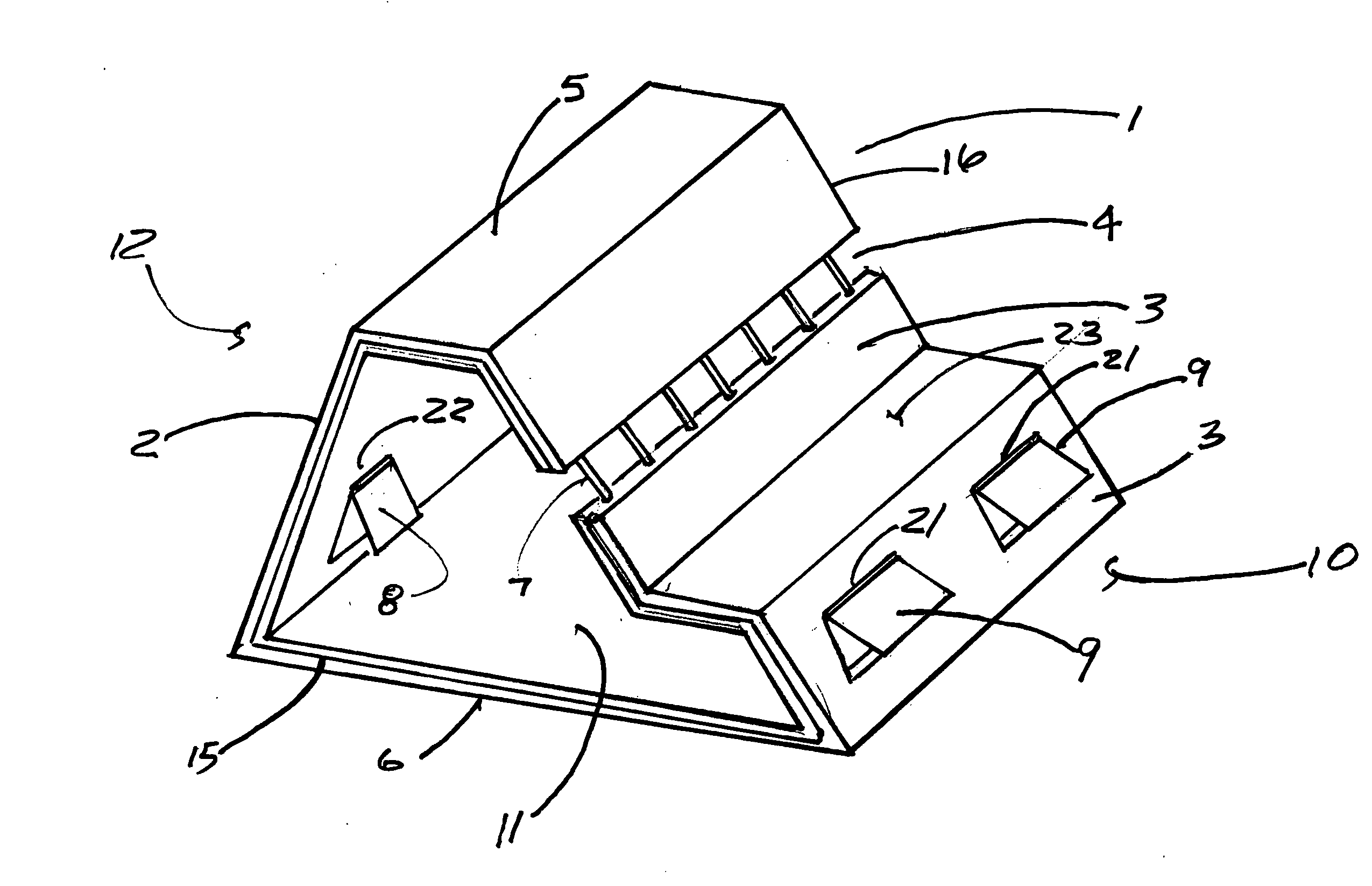
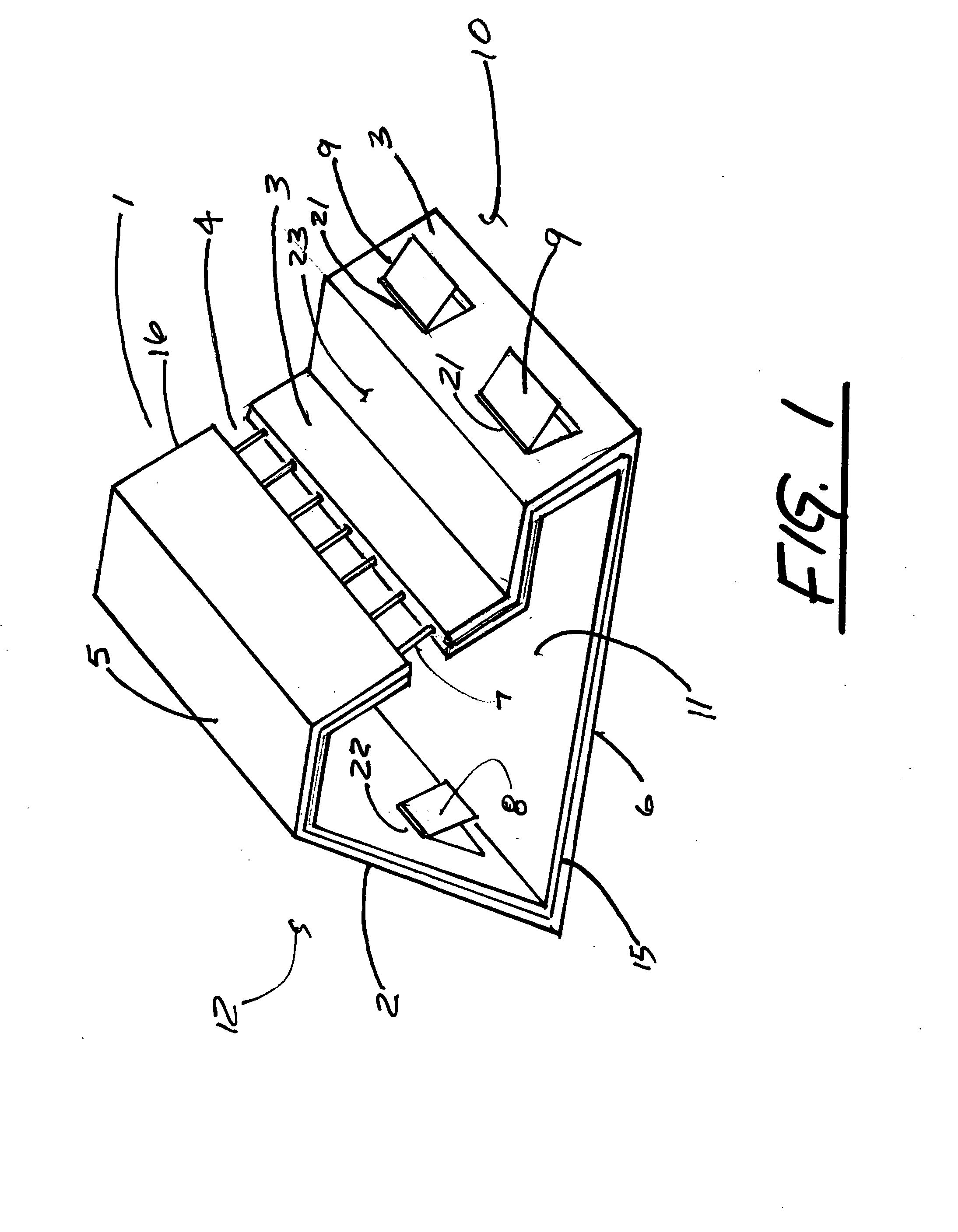
[0018]FIG. 1 shows a perspective view of a prefabricated section 1 of the inventive lightweight concrete structure. The prefabricated section 1 has a protected surface 2 and an unprotected surface 3. This embodiment also depicts an optional horizontal surface 23. Also shown is a top side 5 and a bottom side 6. It is understood that the unprotected surface 3 is on the side 10 of the prefabricated section 1 which would receive or face flood or storm surge waters, and the protected surface 2 is on the side 12 of the prefabricated section 1 meant to be protected from flood or storm surge waters. It is also understood that the prefabricated section 1 is intended to be used with a multiplicity of prefabricated sections 1 connected end to end such that the left end 15 of a section 1 would connect to the right end 16 of an adjacent section 1 in continuous fashion for the length of the desired land to be protected from flood or storm surge waters.

[0019]Also depicted in FIG. 1 is a continuous...


PUM


Abstract

A levee apparatus and system for impeding and controlling the flow of fluids, primarily the flow of water as experienced in a flood or storm surge consisting of a light weight concrete structure with reinforcing steel rebar depending on the application. It is constructed from prefabricated sections with the tongue and groove ends designed to fit together which, when used in conjunction with a rubber gasket, will produce a water tight seal. The structure would be hollow with an opening along the unprotected face to provide a location for the surge water to enter. The structure would have flap-gates on the protected side and on the unprotected side. This would allow flood waters from the protected side to push open the flap-gate and exit the protected side based on the pressure equalization of the flood waters. Once inside the structure any water would then drain from the structure through the flap-gate on the unprotected side when the surge water diminishes. The structure could be placed simply on top of the existing soils or anchored in place to prevent potential changes in alignment. Two main modifications to this design include utilization of a rubberized base which would allow the top portion of the structure to rise into position, and the adjustment of the flap-gate position to change the use of the structure from solely a flood protection system to a retention control system.

Description

[0001]This application claims priority from U.S. Provisional application Ser. No. 60 / 898,853 (“the '853 application”) filed Feb. 1, 2007. The '853 application is incorporated herein by reference.FIELD OF THE INVENTION[0002]In general, the present invention relates to a levee apparatus and system for impeding and controlling the flow of fluids, primarily the flow of water as experienced in a flood or storm surge.BACKGROUND OF THE INVENTION[0003]The currently available levee designs are limited. The main designs in use are earthen levees or piling supported panels. Earthen levees require large quantities of specific material types for which the source can be difficult to find near the areas of construction, thus in significantly increasing costs of the structure. These earthen levees also require large land acquisitions and can take multiple years for construction. Maintenance will also be required for the structure to continue providing consistent levels of protection. This maintenan...

Claims


Application Information

Patent Timeline
IPC IPC(8): E02B7/00
CPCE02B3/10E02B3/102Y02A10/11
Inventor PHILLIPS, AMANDA
Owner PHILLIPS AMANDA
Why Eureka
Try Eureka