Fuel cell apparatus

a fuel cell and apparatus technology, applied in the direction of fuel cell control, fuel cell, electrical apparatus, etc., can solve the problem of gradual drop of outpu

Inactive Publication Date: 2008-10-02
KK TOSHIBA
View PDF1 Cites 10 Cited by
  • Summary
  • Abstract
  • Description
  • Claims
  • Application Information

AI Technical Summary

Benefits of technology

[0015]According to one aspect of this invention, a fuel cell apparatus comprises: a fuel cell generating electric power, including an electrolyte membrane, a fuel electrode which includes an anode catalyst, which is disposed in one side of the electrolyte membrane, which is supplied with liquid fuel, and which discharges gas generated by a chemical reaction accelerated by the anode catalyst, and an oxidizing agent electrode which includes a cathode catalyst, which is disposed in the other side of the electrolyte membrane, and which is supplied with air; and a control unit controlling a load applied to the fuel cell. The control unit increases the load in at least one of two cases, one case being when electric power generated by the fuel cell lowers below a predetermined reference value and another case being at predetermined time intervals, and stops the increase of the load after elapsing a predetermined time period from the start of the increase of the load.
[0016]In at least one of two cases, one case being when electric power generated by the fuel cell lowers below a predetermined reference value and another case being at predetermined time intervals, the control unit increases the load to generate a state in which oxygen is insufficient in the oxidizing agent electrode of the fuel cell. As a result, oxygen bound to the catalyst of the oxidizing agent electrode is consumed and oxidation of the catalyst of the oxidizing agent electrode is reduced, so that the activity of the catalyst is recovered. The load increase is stopped after a predetermined time period which is thought to be required enough for recovering the fuel cell to generate an output (rated output) with a normal value has passed.

Problems solved by technology

The fuel cell has such a problem that its output lowers gradually in accordance with elapsing of its operation time.

Method used


Image

  • Fuel cell apparatus
  • Fuel cell apparatus
  • Fuel cell apparatus

Examples


Embodiment Construction

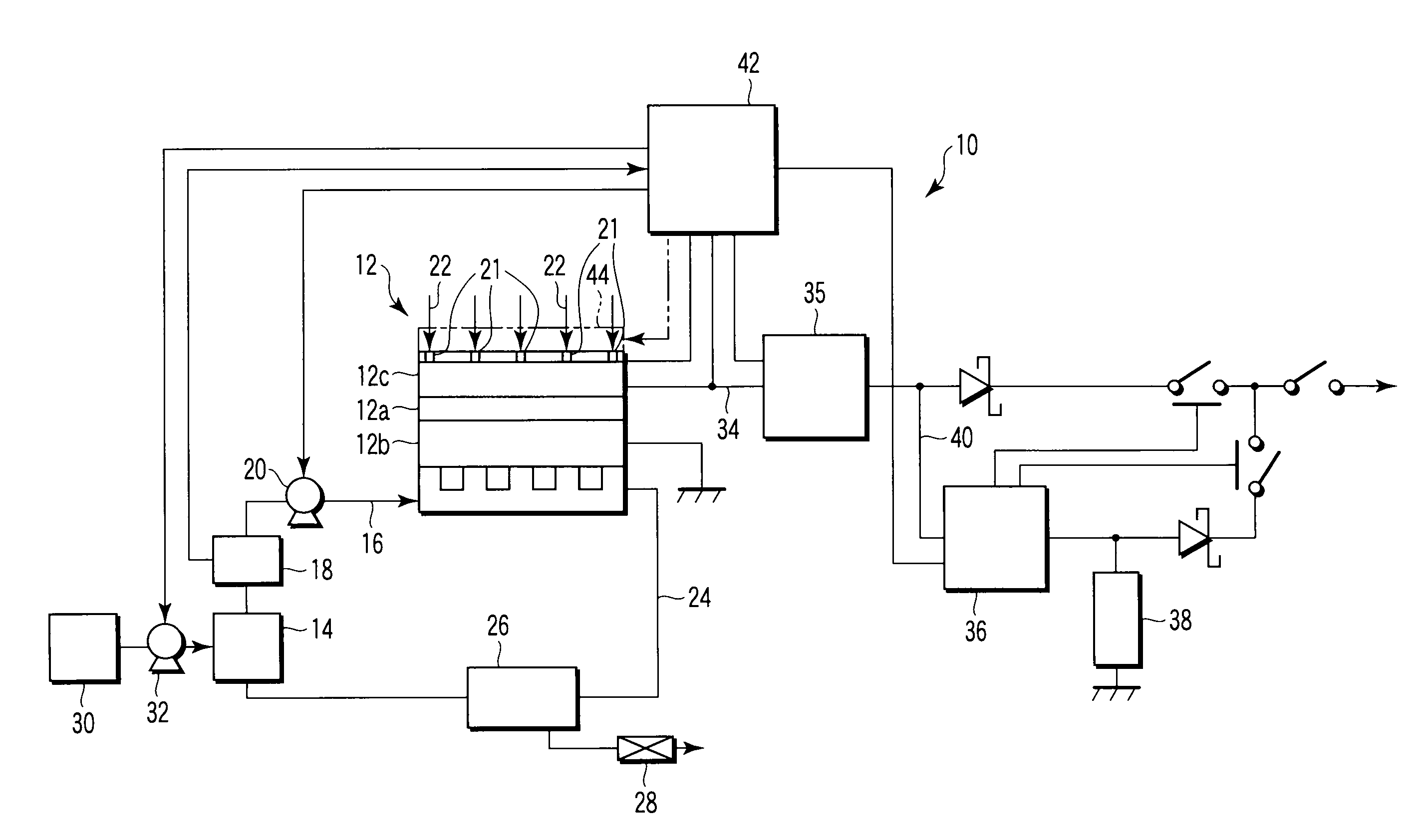
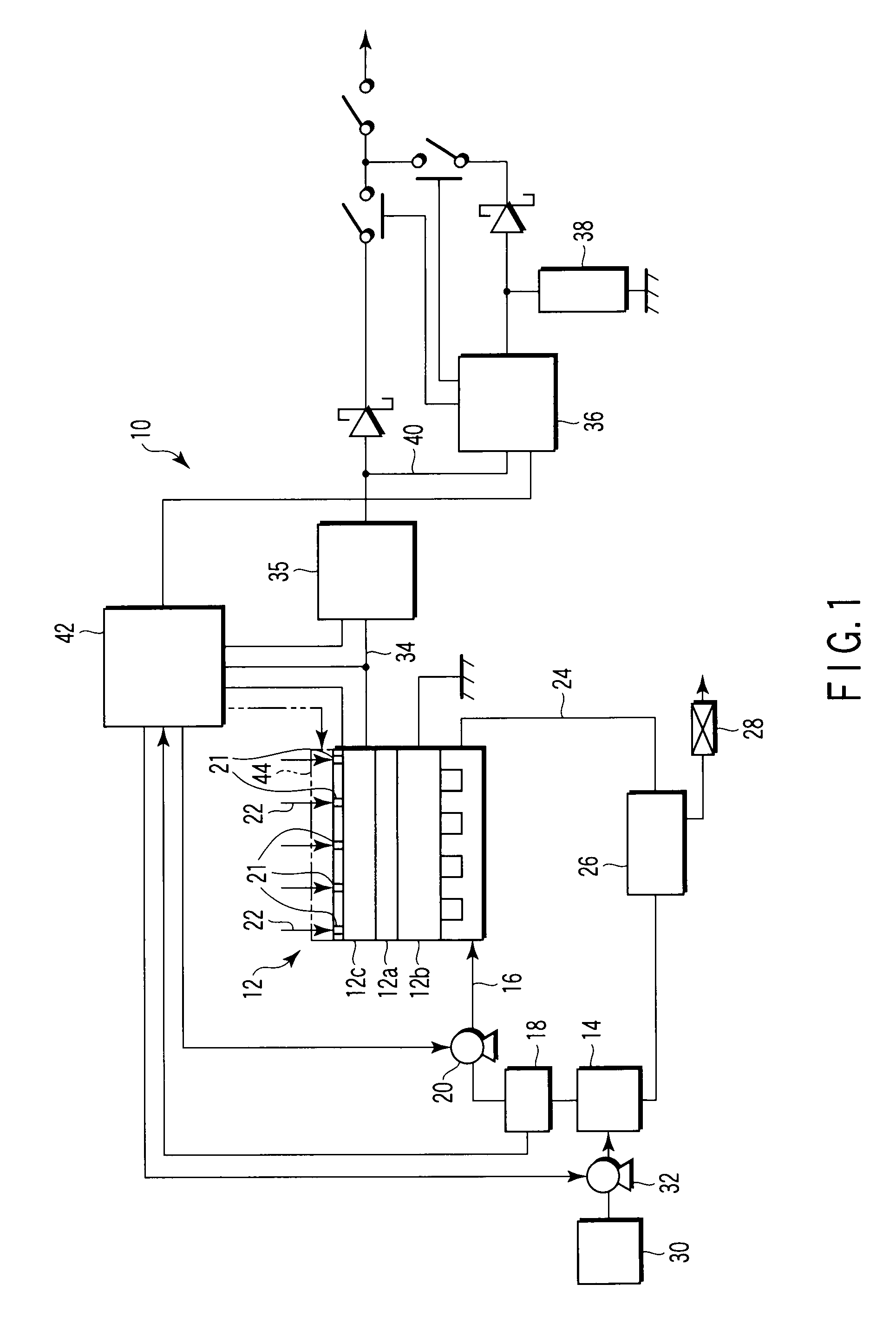
[0022]In FIG. 1, the whole configuration of a fuel cell apparatus 10 according to an embodiment of the present invention is schematically shown.

[0023]The fuel cell apparatus 10 is provided with a fuel cell 12. The fuel cell 12 includes an electrolyte membrane 12a, a fuel electrode 12b which includes an anode catalyst, which is disposed in one side of the electrolyte membrane 12a, which is supplied with liquid fuel, and which discharges gas generated by a chemical reaction accelerated by the anode catalyst, and an oxidizing agent electrode 12c which includes a cathode catalyst, which is disposed in the other side of the electrolyte membrane, and which is supplied with air. The fuel cell apparatus 10 uses methanol-water solution as liquid fuel to generate electric power. The methanol-water solution is obtained by diluting, for example, methanol (CH3OH) with water (H2O) by several % to several tens %. The electrolyte membrane 12a is provided by a polymer membrane with proton conductivi...


PUM

PropertyMeasurementUnit
electric poweraaaaaaaaaa
voltageaaaaaaaaaa
poweraaaaaaaaaa

Abstract

A fuel cell apparatus includes a fuel cell generating electric power, and including a fuel electrode which includes an anode catalyst, which is disposed in one side of an electrolyte membrane, which is supplied with liquid fuel, and which discharges gas generated by a chemical reaction accelerated by the anode catalyst, and an oxidizing agent electrode which includes a cathode catalyst, which is disposed in the other side of the electrolyte membrane, and which is supplied with air, and a control unit controlling a load applied to the fuel cell. The control unit increases the load in at least one of two cases, one case being when electric power generated by the fuel cell lowers below a predetermined reference value and another case being at predetermined time intervals, and stops the increase of the load after elapsing a predetermined time period from the start of the increase of the load.

Description

CROSS-REFERENCE TO RELATED APPLICATIONS[0001]This application is based upon and claims the benefit of priority from prior Japanese Patent Application No. 2007-082646, filed Mar. 27, 2007, the entire contents of which are incorporated herein by reference.BACKGROUND OF THE INVENTION[0002]1. Field of the Invention[0003]This invention relates to a fuel cell apparatus including a fuel cell.[0004]2. Description of the Related Art[0005]A fuel cell has been known, which includes an electrolyte membrane, a fuel electrode including an anode catalyst and being disposed in one side of the electrolyte membrane, the fuel electrode being supplied with liquid fuel and discharging gas generated by a chemical reaction accelerated by the anode catalyst, and an oxidizing agent electrode including a cathode catalyst and being disposed in the other side of the electrolyte membrane, the oxidizing agent electrode being supplied with air. And, the fuel cell uses methanol-water solution obtained by diluting,...

Claims


Application Information

Patent Timeline
Patent Type & Authority Applications(United States)
IPC IPC(8): H01M8/04
CPCH01M8/04559H01M8/04552H01M8/04186H01M8/04873Y02E60/523H01M8/04089H01M8/04589H01M8/0494H01M8/0491H01M8/04298H01M8/04753H01M8/1011H01M8/04902H01M8/04238H01M8/04194H01M8/0488H01M8/04447H01M8/04619H01M8/04104Y02E60/50
Inventor TOMIMATSU, NORIHIROAKITA, MASATOYAGI, RYOSUKE
Owner KK TOSHIBA
Why Eureka
Try Eureka