Battery pack

a battery pack and battery technology, applied in the field of batteries, can solve the problems of excessive load on the engaging members provided between the battery pack and the engaging member, affecting the accuracy of data communication, etc., to achieve the effect of accurate id detection

Active Publication Date: 2008-10-02
SONY CORP
View PDF8 Cites 69 Cited by
  • Summary
  • Abstract
  • Description
  • Claims
  • Application Information

AI Technical Summary

Benefits of technology

[0040]In accordance with the present invention, especially the one embodiment of the invention, the fourth terminal portion constituting an ID terminal is disposed proximate to the fifth terminal portion cons

Problems solved by technology

However, where the communication terminals are arranged side by side with the electrode terminals, electromagnetic radiation from the electrode terminals or electrode tabs connected to the battery cells may influence heavily or hamper the accurate data communication.
In the business-use camcorders and the like, therefore, the loads exerted on the engaging members provided between the battery pack and the battery mounting portion to which the battery pack is attached have been increasing, and, when vibration is generated on the apparatus main body side during use, excessive loads would be exerted on the engaging members.
When an engaging portion formed in a battery pack is enlarged in size, the engaging portion protrudes largely to the inner side, so that the circuit board disposing region would be narrowed, restrictions would be imposed on mounting regions or patterning regions for circuit elements, and the degree of freedom in designing the circuit board would be spoiled.
In addition, if the circuit board is disposed while avoiding the engaging portion, the battery pack would be enlarged in size accordingly, and a dead space would be generated between the circuit board and the battery pack.
However, disposing the electrode members at the bottom surface of the recessed surface portion has been found unsatisfactory for preventing the electrode members from short-circuiting or being broken.
Besides, in the case where the electrode member is configured as a metallic bearing, the insertion of terminal pins constituting the electrode terminals on the battery mounting portion side into opening ends of the metallic bearings exposed from the bottom surface of the recessed surface portion could not be smoothly carried out, due to interference of the terminal pins with the bottom surface or the like.
However, where there are a plurality of spare battery p

Method used


Image

  • Battery pack
  • Battery pack
  • Battery pack

Examples


Embodiment Construction

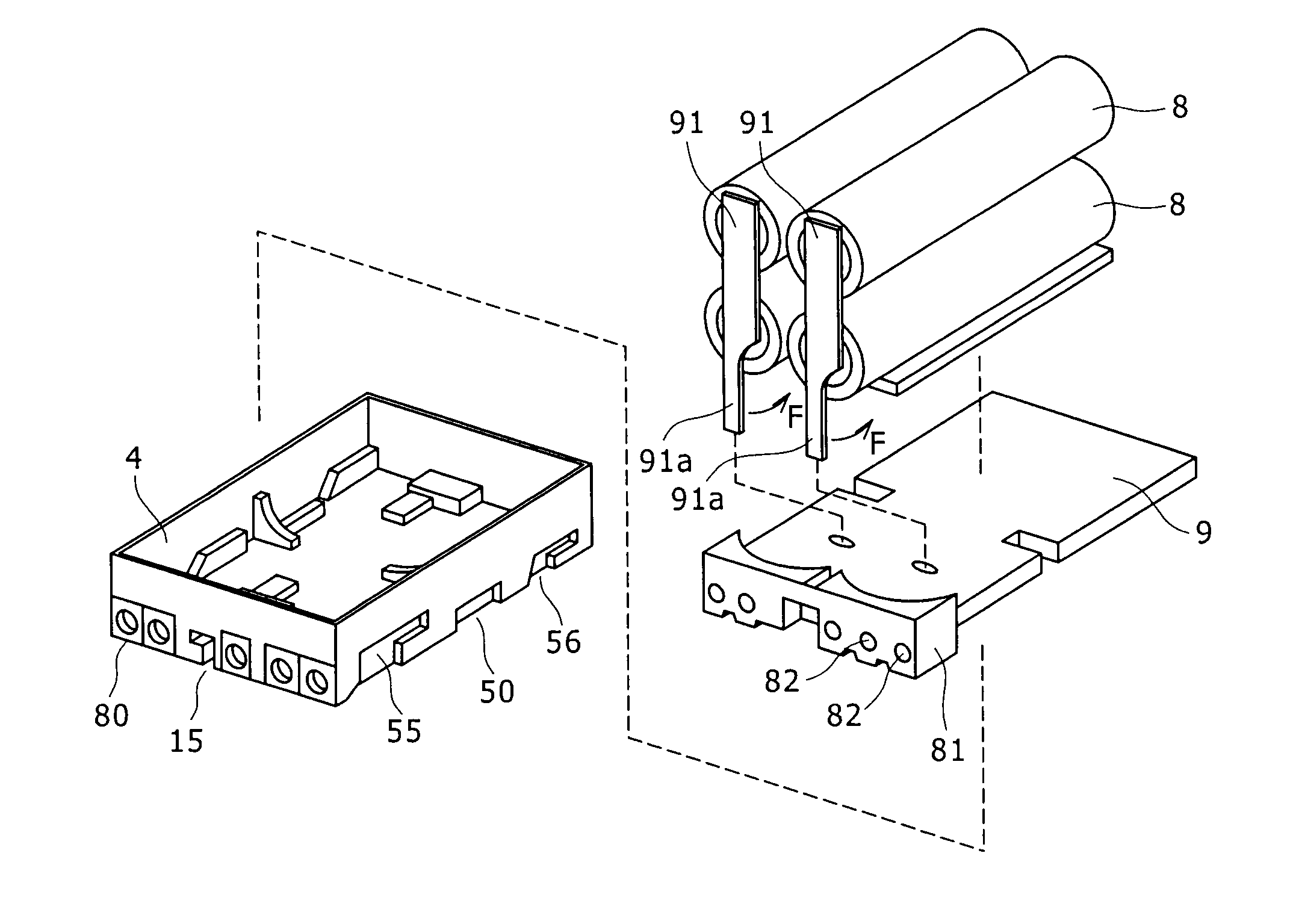
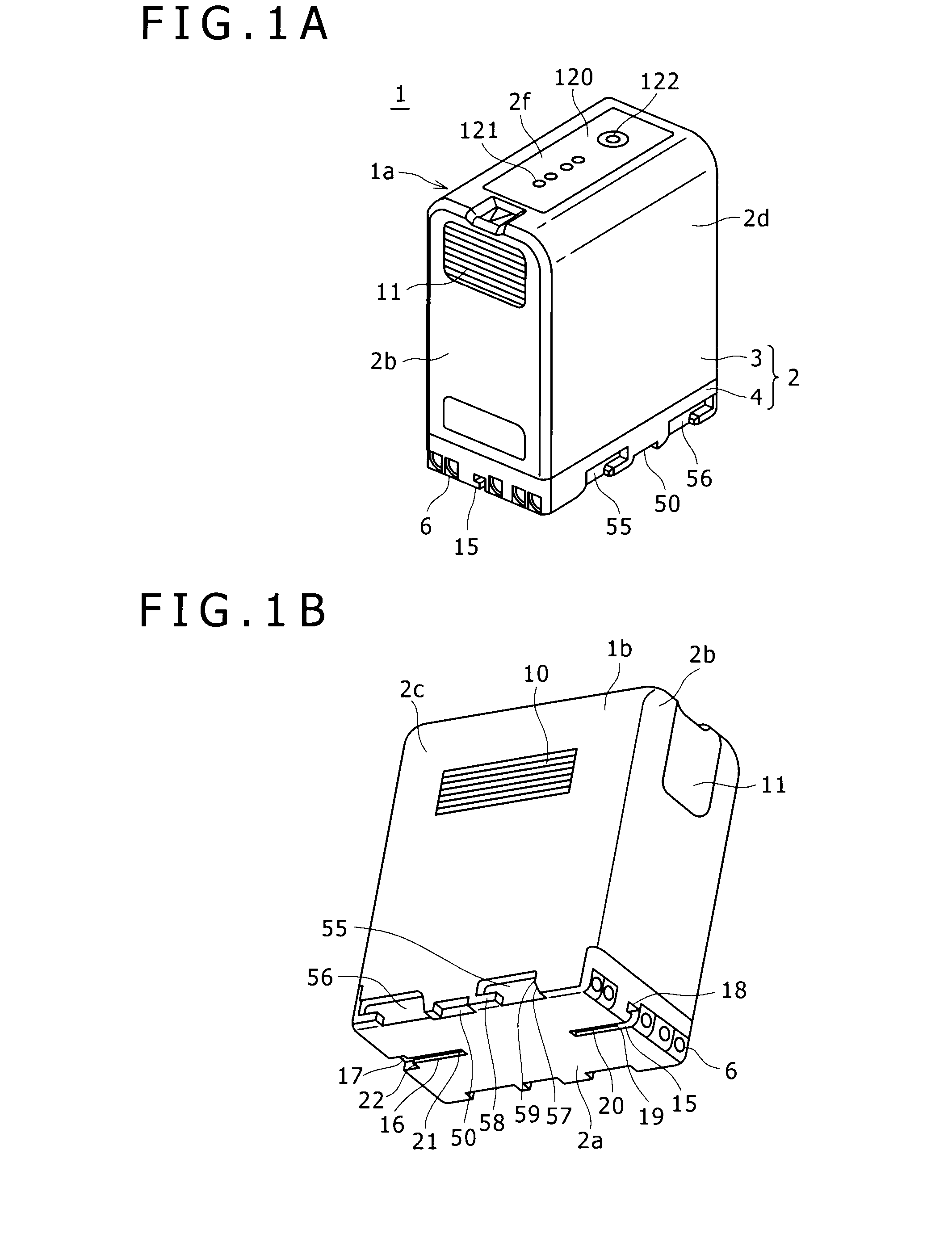
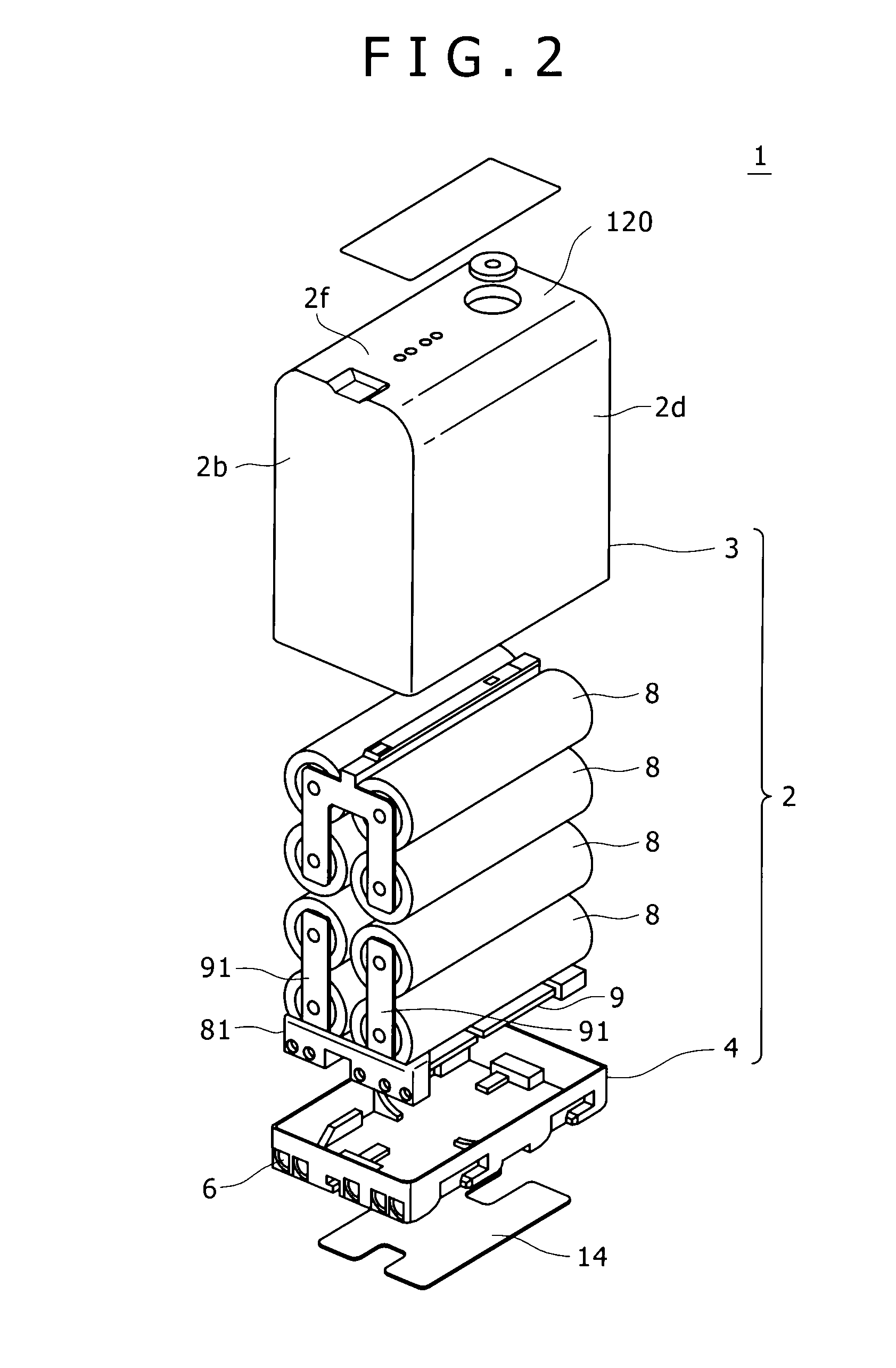
[0066]Now, a battery pack based on embodiments according to the present invention will be described in detail below, referring to the drawings. As shown in FIGS. 1A and 1B, the battery pack 1 has a housing 2 containing battery cells therein and formed in a substantially rectangular shape, with terminal holes in a front surface thereof. As shown in FIG. 2, the housing 2 has an upper cover 3 and a lower case 4 abuttingly coupled to each other, and a plurality of battery cells 8 composed of lithium ion secondary batteries and a circuit board 9 on which a protective circuit, an SMBus (System Management Bus) controller, an ID resistor and the like are mounted and which is provided with an SMBus line are contained in the housing 2. Besides, as shown in FIGS. 1A, 1B, 3A and 3B, the battery packs 1 are prepared in two kinds, namely, for example, large size battery packs 1a and small size battery packs 1b made to be different from each other in electric capacity according to the number of th...


PUM


Abstract

In the present invention, there is provided a battery pack including first to fifth terminal portions sequentially arrayed at one side surface of a housing, wherein the first terminal portion formed on one end side of the one side surface is a positive electrode terminal, the fifth terminal portion formed on the other end side is a negative electrode terminal, the fourth terminal portion formed adjacently to the fifth terminal portion is an ID terminal, and the fourth terminal portion and the fifth terminal portion are proximate to each other; and a guide portion for guiding the loading and unloading of the battery pack into and from a battery mounting portion is formed substantially in the center of the one side surface in array with the terminal portions, and the third terminal portion arranged centrally is formed at a position deviated toward the one end side or the other end side.

Description

CROSS REFERENCES TO RELATED APPLICATIONS[0001]The present invention contains subject matter related to Japanese Patent Application JP 2007-095323, Japanese Patent Application JP 2007-095331, Japanese Patent Application JP 2007-095327, Japanese Patent Application JP 2007-095321, Japanese Patent Application JP 2007-095322, and Japanese Patent Application JP 2007-095324 which are filed in the Japan Patent Office on Mar. 30, 2007, the entire contents of which being incorporated herein by reference.BACKGROUND OF THE INVENTION[0002]1. Field of the Invention[0003]The present invention relates to a battery pack which is formed so that it can be attached to and detached from an electronic apparatus and in which battery cells for supplying driving electric power to the apparatus main body is contained.[0004]2. Description of the Related Art[0005]As portable electronic apparatuses such as digital still cameras and camcorders, there have widely been used those which are provided with a battery ...

Claims


Application Information

Patent Timeline
IPC IPC(8): H01M2/02H01M50/296H01M50/528
CPCH01M2/105H01M2/30Y02E60/12H01M2/1055H01M10/425Y02E60/10H01M50/213H01M10/488H01M10/482H01M50/296
Inventor ENARI, MASAYUKISUZUKI, KATSUHIROMINAMI, HIDENORI
Owner SONY CORP
Why Eureka
Try Eureka