

Root canal length measuring apparatus and root canal therapy apparatus
a technology of root canal and measuring apparatus, which is applied in the field of root canal length measuring apparatus and root canal treatment apparatus, can solve the problems of adding the impedance value of the root canal to the difference of the impedance in the root canal, and achieve the effect of high reproducibility
- Summary
- Abstract
- Description
- Claims
- Application Information
AI Technical Summary
Benefits of technology
Problems solved by technology
Method used
Image

Examples
first embodiment
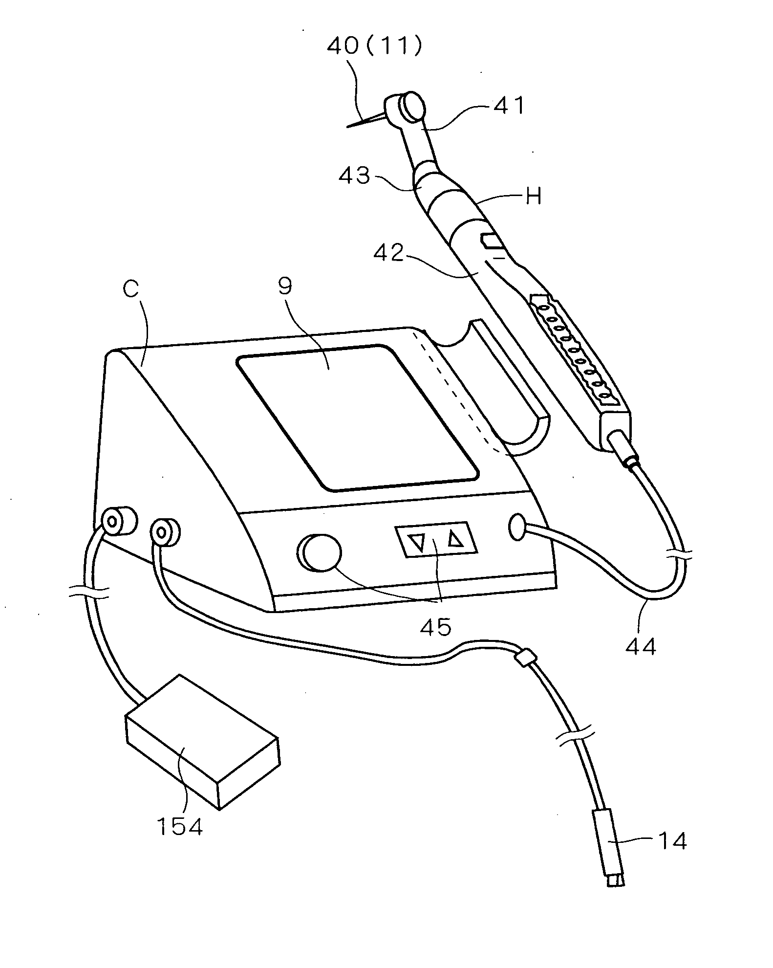
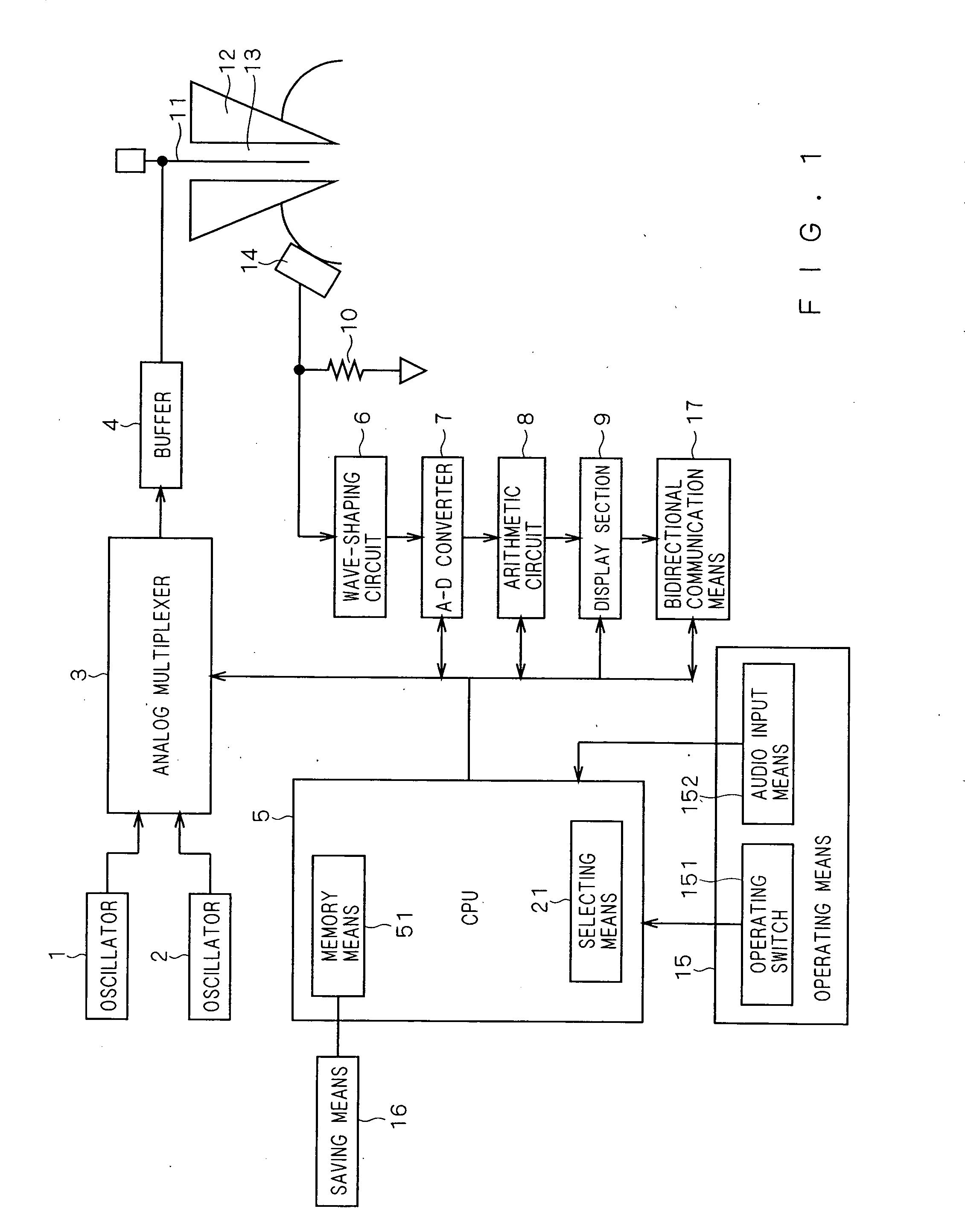
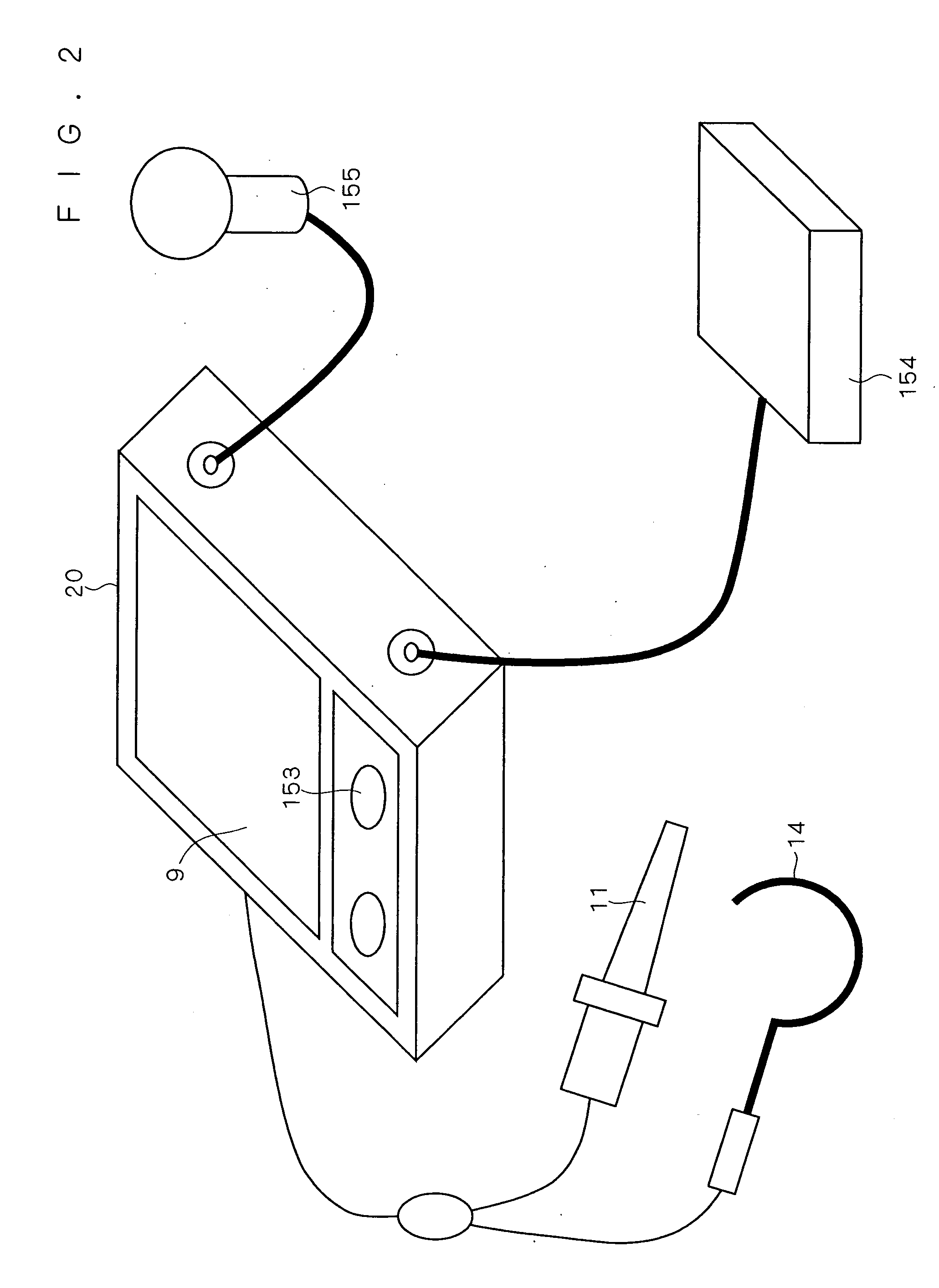
[0053]FIG. 1 is a block diagram illustrating the root canal length measuring apparatus according to the first embodiment. The root canal length measuring apparatus shown in FIG. 1 has an oscillator 1 which outputs a measuring signal having a predetermined frequency, and an oscillator 2 which outputs a measuring signal having a frequency different from the oscillator 1. Further, the root canal length measuring apparatus shown in FIG. 1 has an analog multiplexer 3, a buffer 4 and a CPU 5. The root canal length measuring apparatus shown in FIG. 1 further has a wave-shaping circuit 6, an A-D converter 7, an arithmetic circuit 8, a display section 9 and a detecting resistor 10.
[0054]In the root canal length measuring apparatus shown in FIG. 1, a measurement electrode 11 connected to the buffer 4 is inserted into a root canal 13 of a tooth 12, and a change in impedance in the root canal between an oral electrode 14 connected to the detecting resistor 10 and the measurement electrode 11 is...
second embodiment
[0074]A method for measuring an accurate position from an apex with high reproducibility in the root canal length measuring apparatus according to the second embodiment is described below. In the conventional root canal length measuring apparatus, scale marks 1, 2 and 3 are given to the indicator of the display section. A value indicated by the scale marks is a distance from an apex obtained by an average value of results of measuring the distances from a lot of root canals, and thus these scale marks are given as only guides. For example, even if the display section indicates the scale mark 1, it is not ensured that the measurement electrode is present on a position −1.0 mm away from the apex. As the measurement electrode is moved away from the apex by −2.0 mm and −3.0 mm, its error becomes larger, and thus these scale marks cannot be practically used.
[0075]The conventional root canal length measuring apparatus can approximately accurately detect the apex position although the meas...
third embodiment
[0086]In even some conventional root canal length measuring apparatuses, scale marks are provided to the indicator. These marks show only average values of corresponding root canal positions obtained by detecting impedance values in a lot of root canals, a ratio of the impedance values and a difference in the impedances. Specifically, an example of the conventional root canal length measuring apparatus for detecting the ratio of the impedance in a root canal is described. In the conventional root canal length measuring apparatus, when the measurement electrode 11 arrives at an apex, the ratios of the impedances in the root canal measured at a plurality of frequencies obtains approximately predetermined constant values, and indicates APEX.
[0087]In the conventional root canal length measuring apparatus, scale marks 1, 2 and 3 are given to the indicator correspondingly to the positions −1 mm, −2 mm and −3 mm as average values obtained by measuring a lot of root canals. That is to say, ...
PUM
 Abstract
Description
Claims
Application Information