MRI apparatus and an MRI bed apparatus

a bed apparatus and mri technology, applied in the field of mri apparatus, can solve the problems of reducing the weight of the coil, limiting the weight reduction of the coil, and the test body feeling the mass of the weight, so as to reduce the weight of the high frequency coil and improve the comfort during the capture of images

Inactive Publication Date: 2008-10-09
TOSHIBA MEDICAL SYST CORP
View PDF5 Cites 7 Cited by
  • Summary
  • Abstract
  • Description
  • Claims
  • Application Information

AI Technical Summary

Benefits of technology

[0012]According to the MRI apparatus of the first and second embodiments of this invention, it is possible to maintain a state in which said high frequency coils are kept away from the test body, or are only slightly on the test body, by supporting the high frequency coils, from below, with the support section. This reduces the weight of the high frequency coils on the test body, and it is thus possible to improve comfort during the capture of images.

Problems solved by technology

Hence, in capturing images of the test body covered with a unit (sheet) arranged with RF coils, the test body is covered with the unit's many RF coils, Therefore, the test body feels the massive weight and there is a loss of comfort during the capturing of the images.
But there is a limit to reduce the weight of the coils, due to the increase of RF coils accompanying multichannelizing and the corresponding increase in electrical components involved.
And in cases where the forma and the unit that is arranged with RF coils are shared, the unit that is arranged with RF coils, which is shared with the forma, becomes larger and heavier, and it is difficult for the operator to handle it.
In addition, if the test body is large, it is difficult for the operator to observe the location of the forma across the test body, which is placed on the bed apparatus, on the opposite side from the operator.

Method used


Image

  • MRI apparatus and an MRI bed apparatus
  • MRI apparatus and an MRI bed apparatus
  • MRI apparatus and an MRI bed apparatus

Examples


first embodiment

The First Embodiment

Configuration of the Bed Apparatus

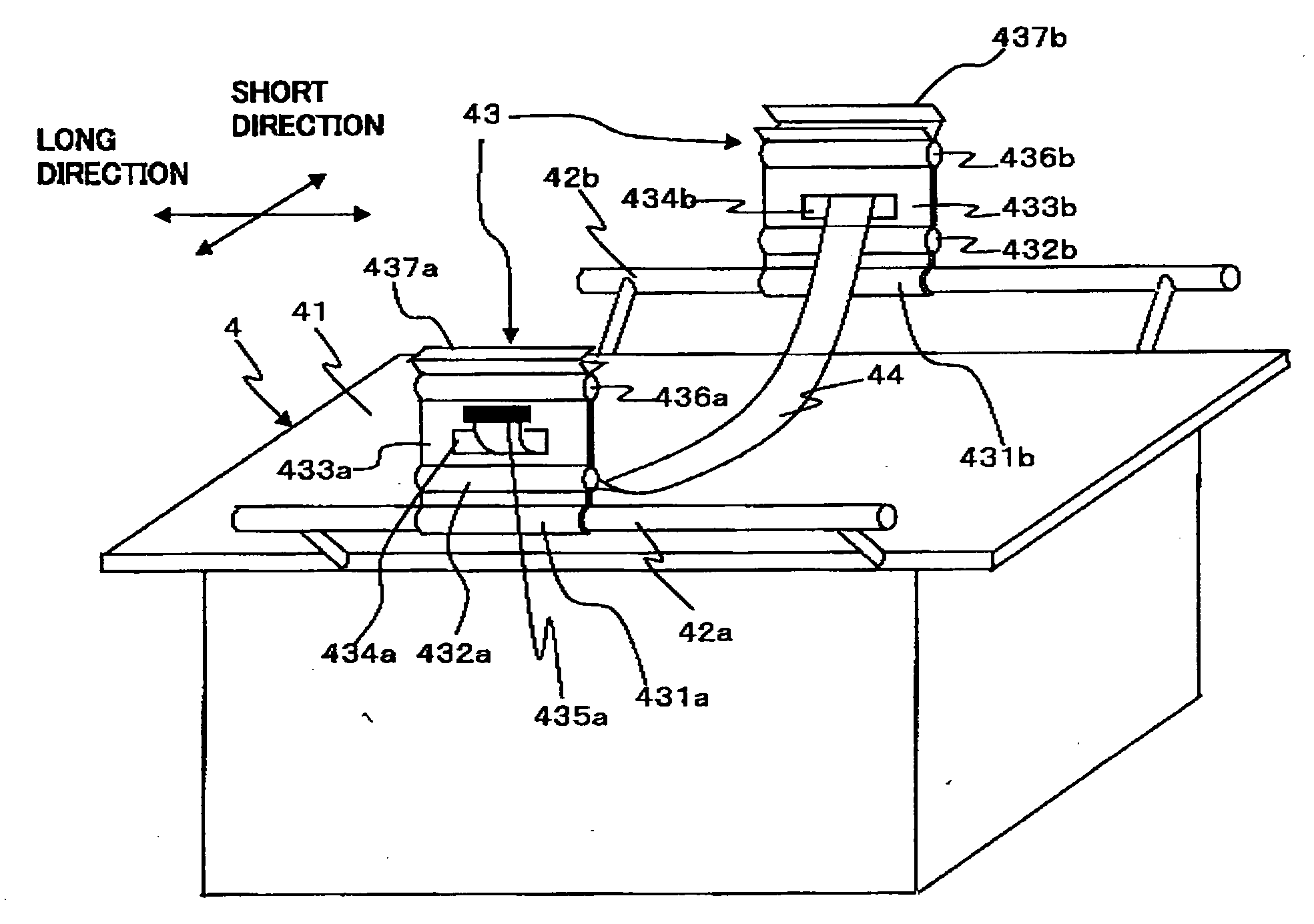
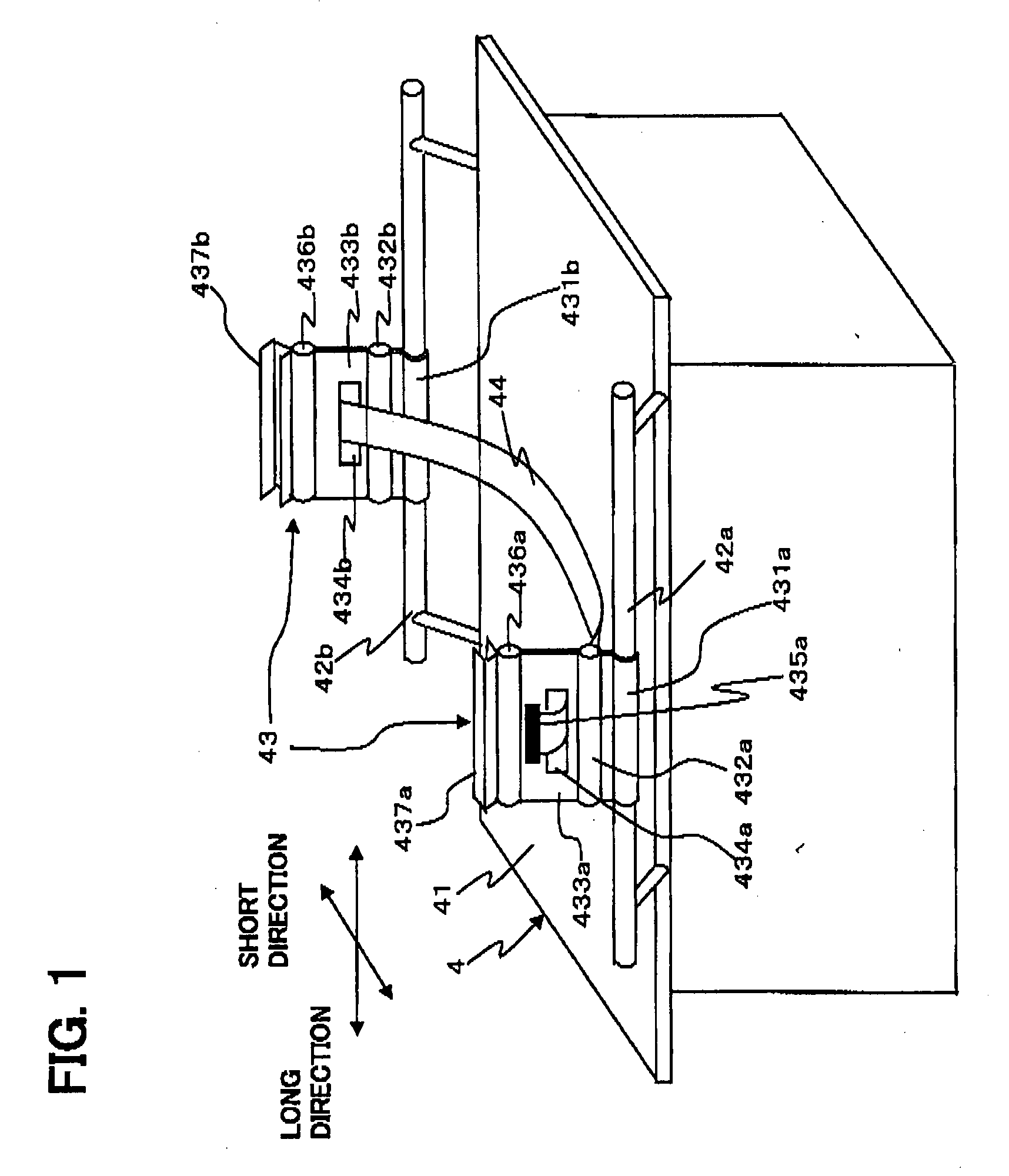
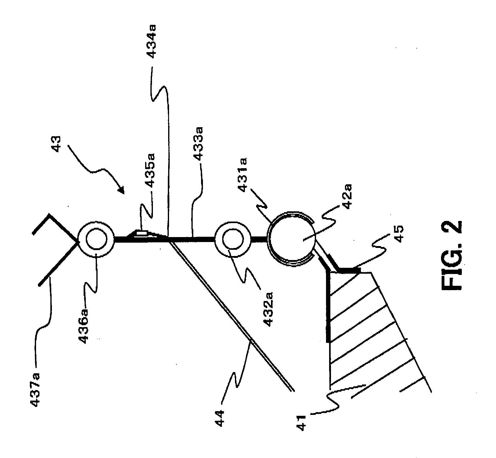
[0018]The configuration of the bed apparatus 4 in this MRI device will be described. FIG. 1 represents an example of the exterior configuration of a support section positioned on a top board 41 of a bed apparatus 4. FIG. 2 represents a cross section diagram of the bed apparatus relating to this embodiment. FIG. 3 is a cross section diagram, in which the test body and RF coils 8 are placed on the bed apparatus relating to this embodiment.

[0019]The bed apparatus 4 shown in FIG. 1 and FIG. 2 is used to support the RF coils 8 with a support section 43 from below. For this purpose, the test body P is placed on top board 4 for the capture of images with the MRI apparatus, and the RF coils 8 are placed on it as shown in FIG. 3.

[0020]RF coils 8 are structured so as to have the shape like a flat board. Furthermore, if both edges are supported from below, RF coils 8 bend in the upward direction or maintain their current state, and is hard ...

second embodiment

The Second Embodiment

[0068]The MRI bed apparatus described here relates to the second embodiment of the present invention. The MRI bed apparatus that relates to the second embodiment is configured so that it is possible to change the height of support section 43 in the first embodiment. Here height refers to the distance from top board 41 to receiving member 437a or to receiving member 437b. A configuration to change the height of support section 43 will be mainly described below. Two support sections 43 that are arranged on both edges of top board 41 have the same configuration, so support section 43, which comprises connection member 431a, hinge section 432a, plate member 433a, slit 434a, buckle 435a, hinge section 436a and receiving member 437a, as shown in FIG. 1, will be described below.

[0069]FIG. 5 describes plate member 433a among support section 43. Support section 43, which relates to the present embodiment, has the same configuration as the one in the first embodiment, exp...


PUM


Abstract

The test body is placed on the top board. The support section has a support post, a hinge section and a receiving member. The hinge section is linked to the edge of the shorter direction of said top board at one edge of the support post and performs a hinge movement in said shorter direction. The receiving member holds said test body and supports RF coils, when it is positioned on the other edge of the support post and said support post is caused to stand up by the hinge movement. The support section is positioned on both edges of said shorter direction of said top board.

Description

BACKGROUND OF THE INVENTION[0001]1. Field of the Invention[0002]The present invention relates to an MRI apparatus for taking MRI images of a subject, and a bed apparatus on which a test body is placed as the subject of the MRI images.[0003]2. Description of the Related Art[0004]MRI (Magnetic Resonance Imaging) apparatus is a medical imaging apparatus such that when the applied magnetic field is applied to a test body placed on the bed apparatus in the static magnetic field, an excitation magnetic field (RF magnetic field) is applied from an excitation magnetic field coil (transmitter RF coil) to obtain nuclear magnetic resonance signals (MR signals) with a nuclear magnetic resonance signal coil (receiver RF coil), and the MRI images (cross-sectional images) of said test body are reconstituted on the basis of the obtained nuclear magnetic resonance signals (MR signals).[0005]If tomography is carried out using such an MRI apparatus, many RF (Radio Frequency) coils need to be placed in...

Claims


Application Information

Patent Timeline
Patent Type & Authority Applications(United States)
IPC IPC(8): G01R33/30A61G7/00
CPCG01R33/30G01R33/307G01R33/34084G01R33/341
Inventor KATO, YUTAKA
Owner TOSHIBA MEDICAL SYST CORP
Why Eureka
Try Eureka