Eos robust bipolar transient clamp

a bipolar transient clamp and robust technology, applied in emergency protective arrangements, electrical appliances, emergency protection arrangements for limiting excess voltage/current, etc., can solve the problems of unattractive total power consumption, unfavorable circuit operation switching noise, and ineffective elements to keep the clamp o

Inactive Publication Date: 2008-10-09
INTERSIL INC
View PDF18 Cites 14 Cited by
  • Summary
  • Abstract
  • Description
  • Claims
  • Application Information

AI Technical Summary

Benefits of technology

[0004]In one embodiment, a bipolar transient clamp is provided. The clamp includes a RC circuit, a clamping circuit and a breakdown circuit. The RC circuit is configured to control the rate of change of clamp. Moreover, the RC circuit is coupled between a first rail and a second rail. The clamping circuit is configured to pass a current from the first rail to the second rail. In addition, the clamping circuit is coupled to be activated by the RC circuit. The breakdown circuit is coupled between the RC circuit and the clamping circuit. The breakdown circuit is configured to increase the transient trigger voltage of the clamping circuit.

Problems solved by technology

In a purely bipolar process used to form a bipolar clamp, there is not an effective element to keep the clamp turned off once power is applied since the clamp has to draw power to keep it turned off.
This makes it unattractive from total power consumption standpoint.
An issue with transient bipolar clamps is the switching noise produced by circuit operation.
The noise could exceed the transient voltage threshold of the clamp causing the ESD clamps to falsely trigger.

Method used


Image

  • Eos robust bipolar transient clamp
  • Eos robust bipolar transient clamp
  • Eos robust bipolar transient clamp

Examples


Embodiment Construction

[0012]In the following detailed description, reference is made to the accompanying drawings, which form a part hereof, and in which is shown by way of illustration specific embodiments in which the inventions may be practiced. These embodiments are described in sufficient detail to enable those skilled in the art to practice the invention, and it is to be understood that other embodiments may be utilized and that logical, mechanical and electrical changes may be made without departing from the spirit and scope of the present invention. The following detailed description is, therefore, not to be taken in a limiting sense, and the scope of the present invention is defined only by the claims and equivalents thereof.

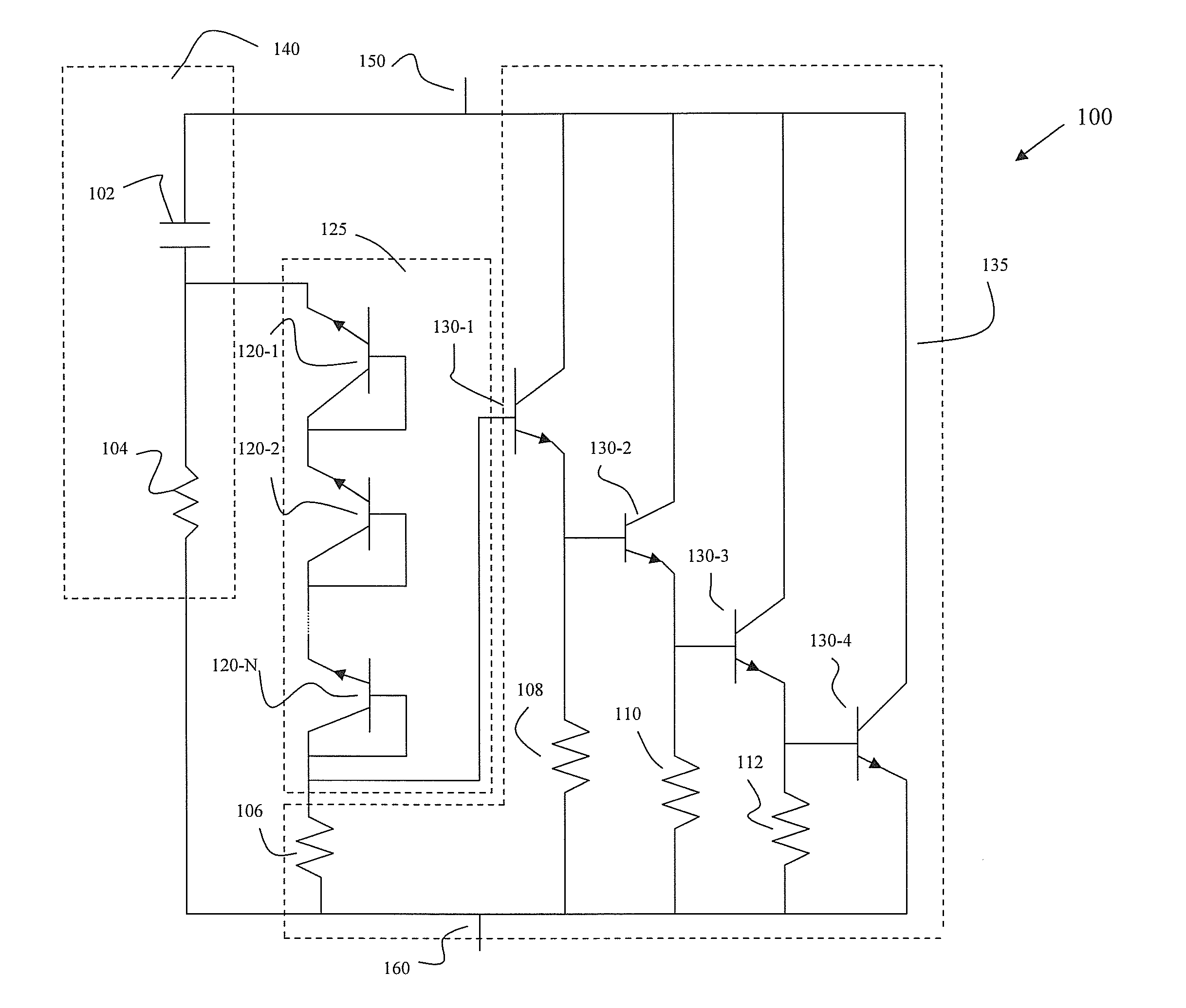
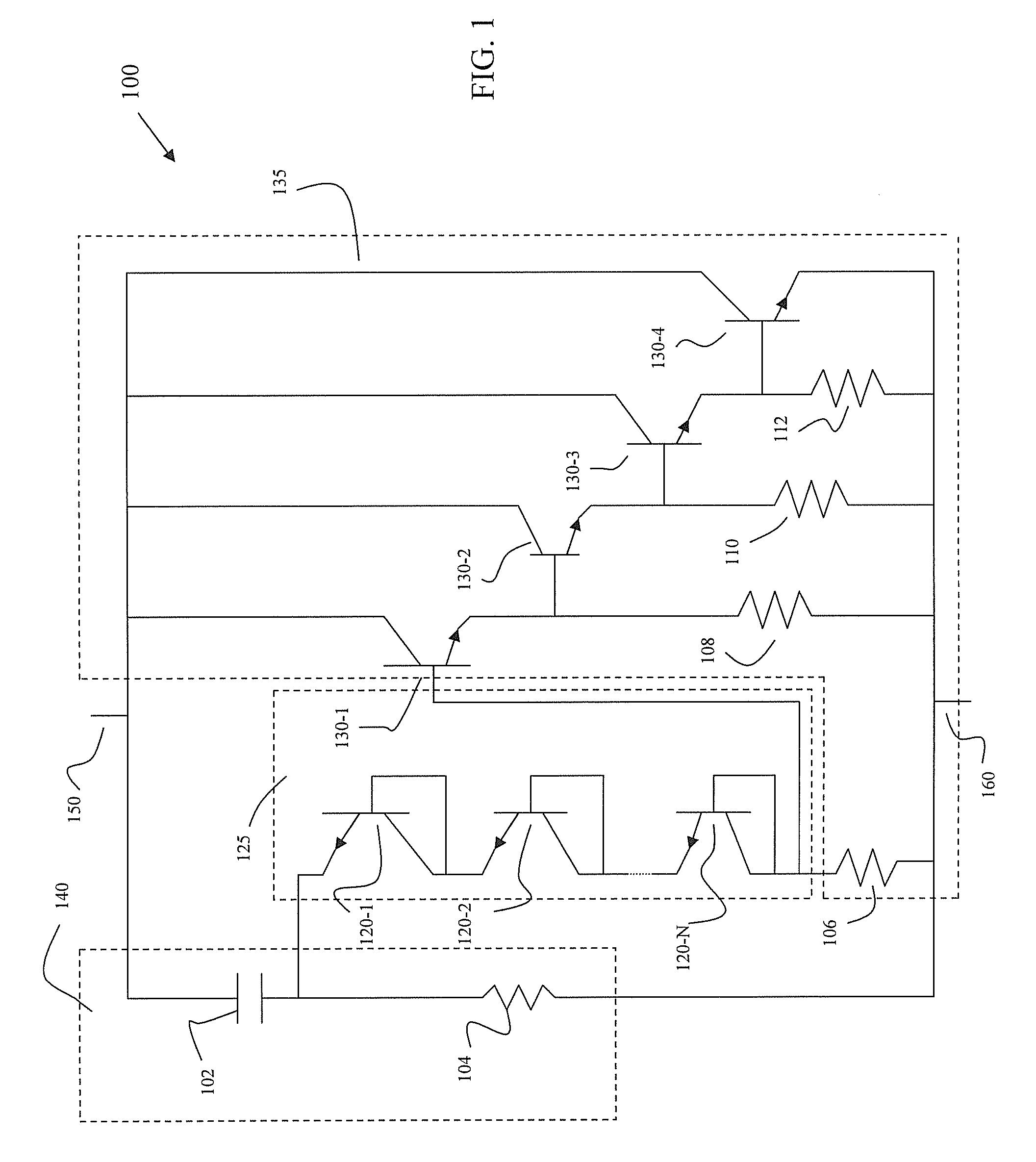
[0013]Embodiments of the present invention increase the required trigger voltage by placing one or more breakdown elements in series with the trigger path allowing a tunable trigger voltage. A higher trigger voltage prevents noise transients from falsely triggering the clamp...


PUM


Abstract

A bipolar transient clamp including a RC circuit, a clamping circuit and a breakdown circuit. The RC circuit is configured to control the rate of change of clamp. Moreover, the RC circuit is coupled between a first rail and a second rail. The clamping circuit is configured to pass a current from the first rail to the second rail. In addition, the clamping circuit is coupled to be activated by the RC circuit. The breakdown circuit is coupled between the RC circuit and the clamping circuit. The breakdown circuit is configured to increase the transient trigger voltage of the clamping circuit.

Description

BACKGROUND [0001]Transient electrostatic discharge (ESD) clamps are very effective with respect to ESD protection because they respond quickly to an ESD event and can clamp well. Moreover, they are easily simulated. Two common types of clamps include a CMOS clamp and a bipolar clamp. In a common CMOS clamp design, an active device is used to keep the main clamping transistor off until needed. In a purely bipolar process used to form a bipolar clamp, there is not an effective element to keep the clamp turned off once power is applied since the clamp has to draw power to keep it turned off. This makes it unattractive from total power consumption standpoint. However, a transient bipolar clamp has its advantage because it can respond to transient voltages of a few volts. In addition, the rise time that a bipolar clamp responds to can be tuned by adjusting the resistance and capacitance of the RC network. An issue with transient bipolar clamps is the switching noise produced by circuit o...

Claims


Application Information

Patent Timeline
Patent Type & Authority Applications(United States)
IPC IPC(8): H02H3/22H02H3/20
CPCH02H9/046
Inventor VINSON, JAMES E.
Owner INTERSIL INC
Why Eureka
Try Eureka