Lens system for LED lights

a technology of led lights and lenses, applied in the direction of point-like light sources, lighting and heating apparatuses, lighting device details, etc., can solve the problem that the light is typically not focused enough to provide efficient lighting for such applications, and achieve the effect of reducing the mold cycle time for fabricating parts, reducing color distribution, and eliminating unevenness

Active Publication Date: 2008-10-09
INNOTEC CORP
View PDF5 Cites 53 Cited by
  • Summary
  • Abstract
  • Description
  • Claims
  • Application Information

AI Technical Summary

Benefits of technology

[0008]The lens portion of the opposite surface and of the concentric flat portion, along with the tapered surface, are configured such that the light reflected internally is reflected back towards the center of the lens, thereby directing the yellow light from the edges of the LED back into the main portion of the light pattern. In this way, the device not only produces a light pattern having a relatively uniform light intensity, but also directs the yellow light back towards the center of the light pattern, thereby eliminating the uneven color distribution found with other collimator systems. The optical device may be molded from a suitable polymer such as an acrylic material. The unique shape of the optical device provides a thin cross section, having the overall shape of a flat dish. Because the device is quite thin, mold cycle times

Problems solved by technology

Although the light produced by a white LED has a color that is acceptable for task lights and the l

Method used


Image

  • Lens system for LED lights
  • Lens system for LED lights
  • Lens system for LED lights

Examples


Embodiment Construction

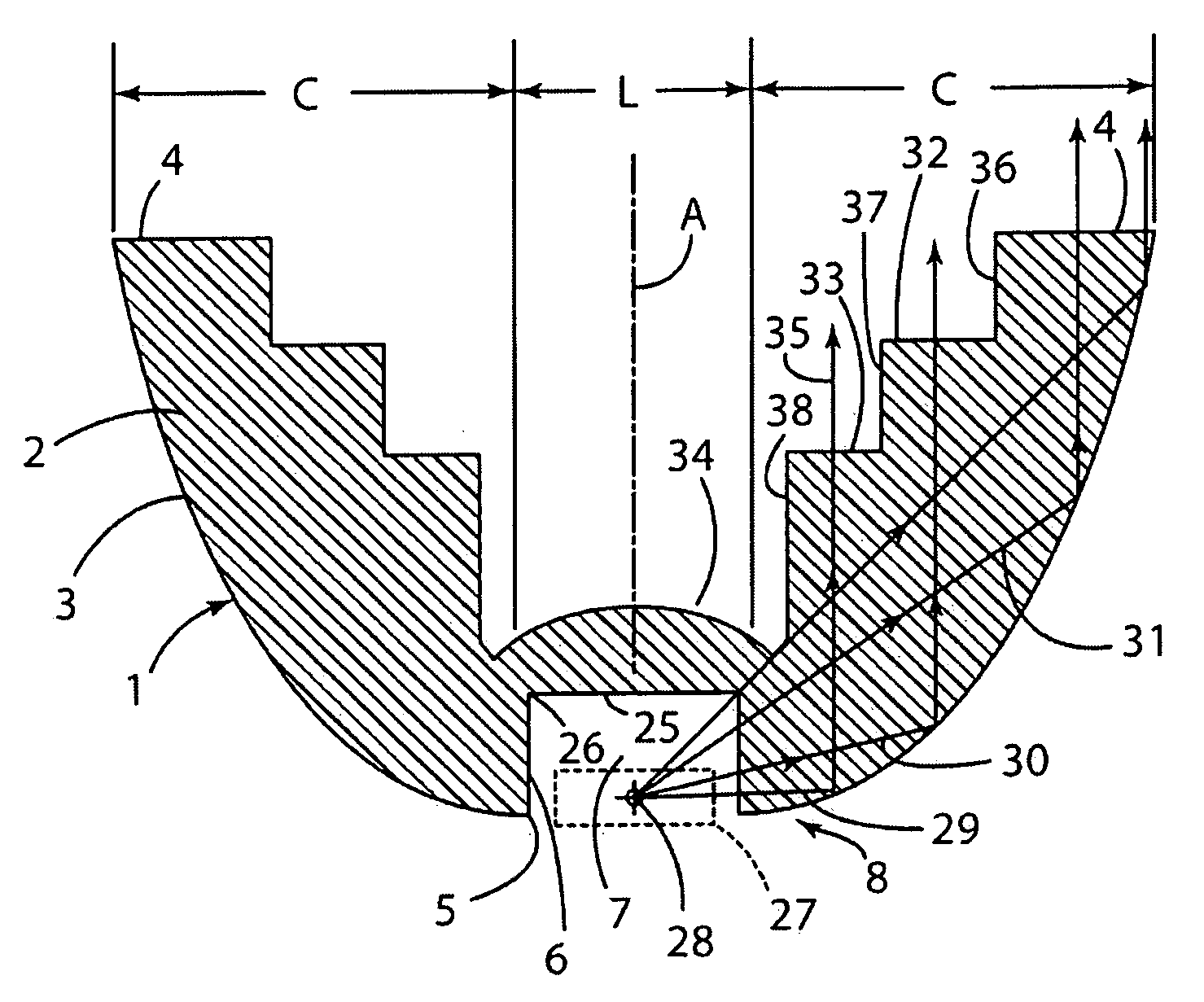
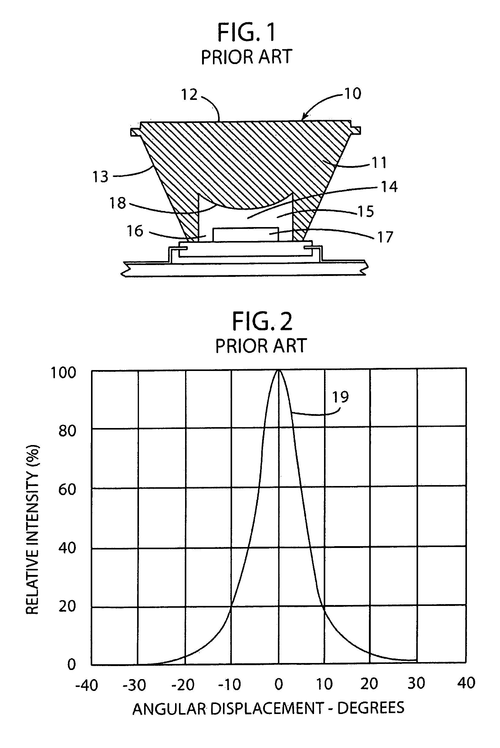
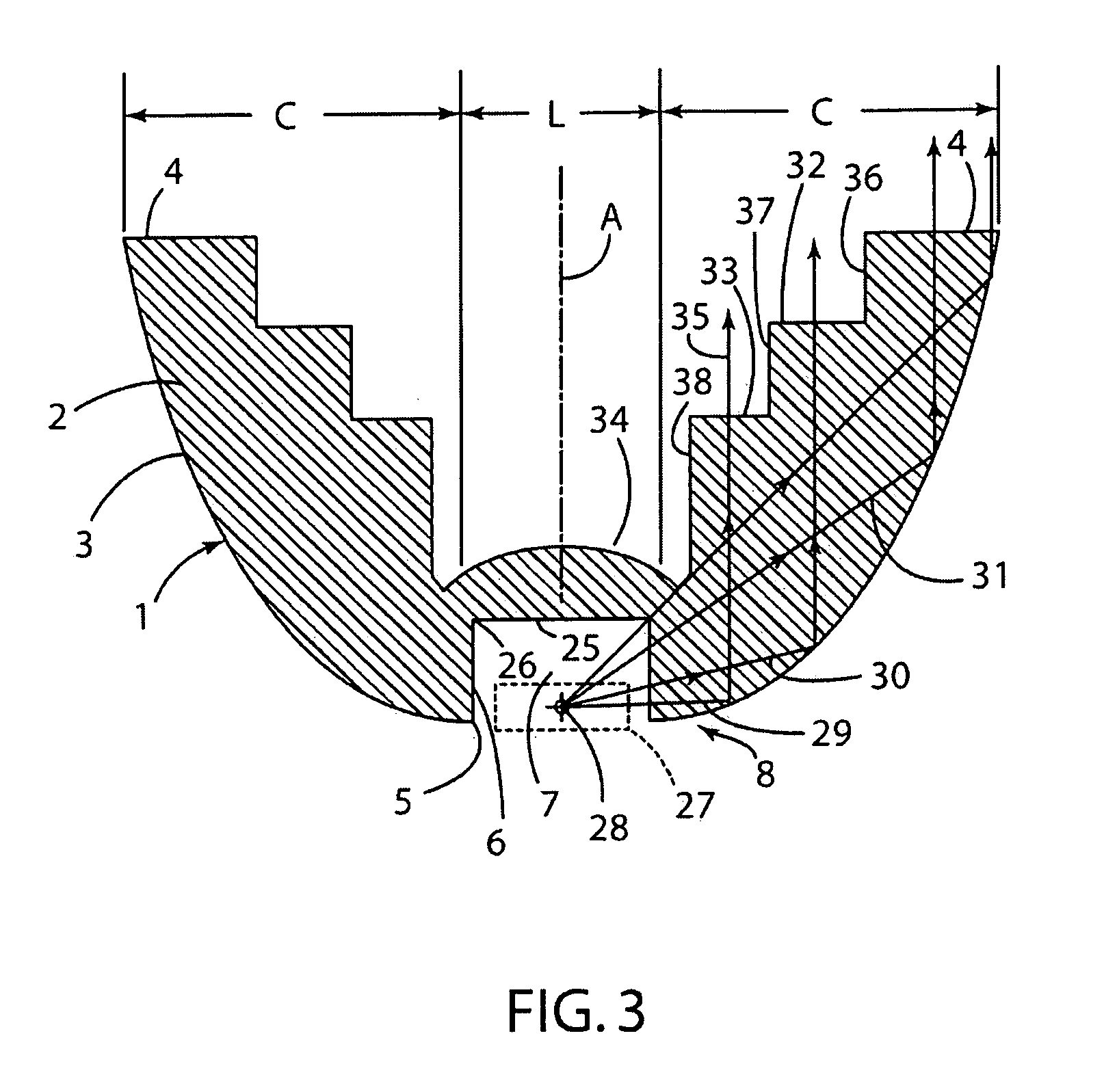
[0022]For purposes of description herein, the terms “upper,”“lower,”“right,”“left,”“rear,”“front,”“vertical,”“horizontal,” and derivatives thereof shall relate to the invention as oriented in FIGS. 3 and 4, However, it is to be understood that the invention may assume various alternative orientations and step sequences, except where expressly specified to the contrary. It is also to be understood that the specific devices and processes illustrated in the attached drawings and described in the following specification are simply exemplary embodiments of the inventive concepts. Hence, specific dimensions and other physical characteristics relating to the embodiments disclosed herein are not to be considered as limiting.

[0023]With reference to FIG. 3, an optical device 1 according to one aspect of the present invention includes a body 2 made of a transparent acrylic material, or other suitable light-transmitting material. The body 2 includes a tapered outer surface 3 extending from an e...


PUM


Abstract

An optical device for distributing light produced by a white LED or other light-producing device includes a lens portion that refracts the light to provide a desired light intensity distribution, and a collimating portion that internally reflects light from the white LED. The optical device may be molded from an acrylic polymer material or the like. The reduced thickness of the device facilitates low cycle times and reduces warpage or other distortion that would otherwise be generated during the molding process.

Description

CROSS-REFERENCE TO RELATED APPLICATIONS[0001]This application claims the benefit of U.S. Provisional Application No. 60 / 910,691, filed on Apr. 9, 2007, entitled LENS SYSTEM FOR LED LIGHTS, the entire contents of which are incorporated herein by reference.BACKGROUND OF THE INVENTION[0002]“White” LEDs have been used in numerous devices / applications such as flashlights, task lights for motor vehicles and the like. White LEDs generally include a blue LED with a phosphor coating that emits yellow light which mixes with the blue light to provide light that is perceived to be primarily white, with a slight bluish tint. Another type of white LED utilizes a combination of blue, red, and green LEDs to produce white light. Due to the efficiency of white LEDs, the use of white LEDs in applications such as vehicles and the like having a limited supply of electrical power has been increasing.[0003]Although the light produced by a white LED has a color that is acceptable for task lights and the li...

Claims


Application Information

Patent Timeline
IPC IPC(8): F21V7/00F21V5/04
CPCF21V5/04F21V7/0091F21Y2101/02F21Y2115/10
Inventor DANEK, JOSHUA M.VEENSTRA, THOMAS J.
Owner INNOTEC CORP
Why Eureka
Try Eureka