Method and system for detecting water system leaks

a technology for water system leaks and detection methods, applied in the direction of fluid tightness measurement, functional valve types, instruments, etc., can solve problems such as excessive humidity or standing water, water system leaks, etc., to prevent false alarms or appliance damage, accurate distinction between short-term usage flow and long-term leakage, and reduce the slope of decompression

Active Publication Date: 2008-10-16
FORD MICHAEL BRENT
View PDF18 Cites 35 Cited by
  • Summary
  • Abstract
  • Description
  • Claims
  • Application Information

AI Technical Summary

Benefits of technology

[0009]The above objectives of detecting low flow water leaks is accomplished in a method and system. To detect low-flow leaks, the system includes a back-pressure detector that detects when the pressure in the household side of the water system drops, when an electronically controlled valve between the water supply and the household side of the water system has been closed. When the electronically controlled valve is open, inconvenience, false alarms or appliance damage are prevented by detecting electrical current usage by water-using devices and qualifying flow detection or humidity detection by the leakage detection system. The back-pressure detection system may include an extra bladder / balloon / diaphragm system that maintains a lower slope of decompression with flow, so that more accurate distinctions between short-term usage flow and long-term leaks can be determined.

Problems solved by technology

However, an excess amount of humidity can indicate the presence of standing water or a roof leak that should be corrected or mold growth and other damage to building materials may quickly result.
Water system leaks can also contribute to an excessive amount of humidity or standing water.
However, the systems described in the above-incorporated U.S. Patent Applications use a flow meter to detect water leaks and it is possible that a very low level of water flow from a plumbing system leak can still cause damage, such as by promoting mold growth.

Method used


Image

  • Method and system for detecting water system leaks
  • Method and system for detecting water system leaks
  • Method and system for detecting water system leaks

Examples


Embodiment Construction

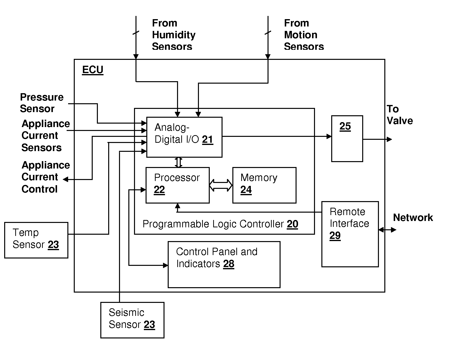
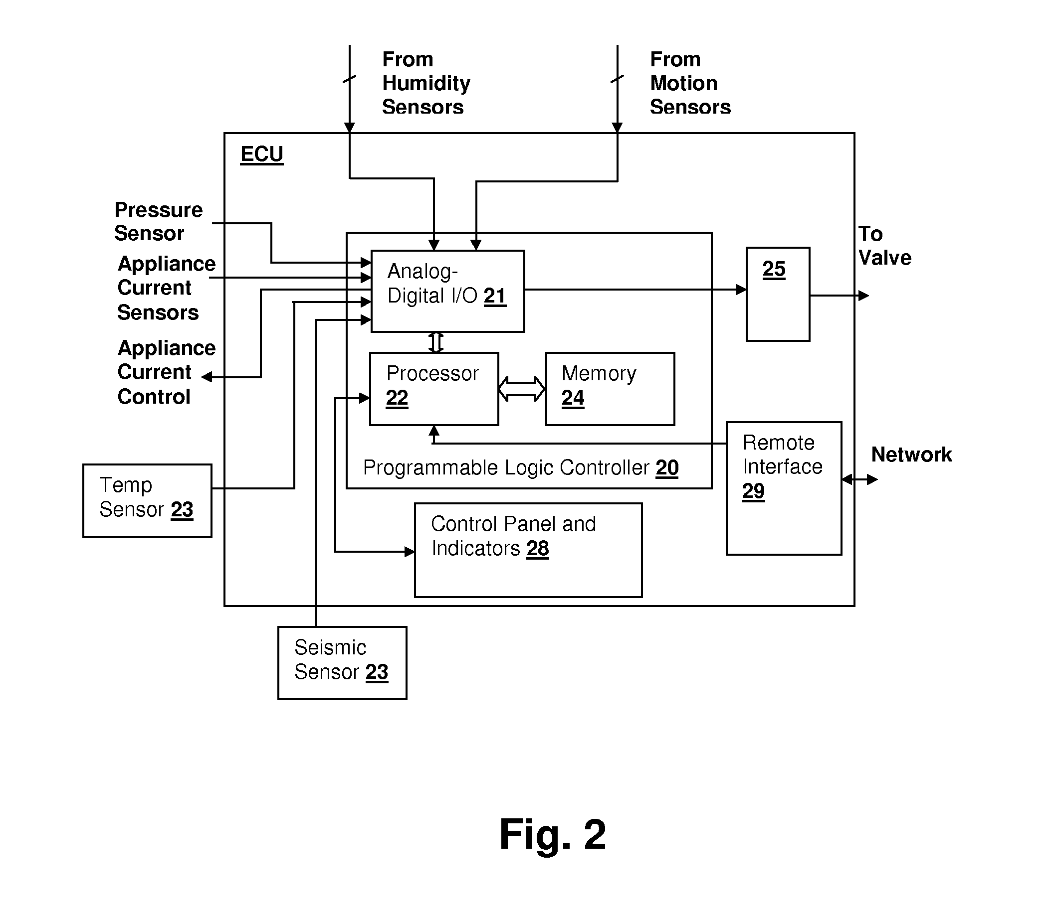
[0015]The present invention concerns techniques for detecting very low flow water system leaks in a building water system. An electrically controlled valve is used to shut off the water system, and a pressure sensor is used to monitor drops in water pressure on the building water system side of the valve. False alarms are qualified by using one or more motion sensors to determine whether human activity is present in the building, which prevents the generation of false alarms due to normal water use activity. Humidity levels may also be additionally monitored as an indication of the possible presence of water system or structure leaks. The electrically controlled valve is shut off in response to an indication that the building is unoccupied or there is no human activity, for example when household occupants are sleeping.

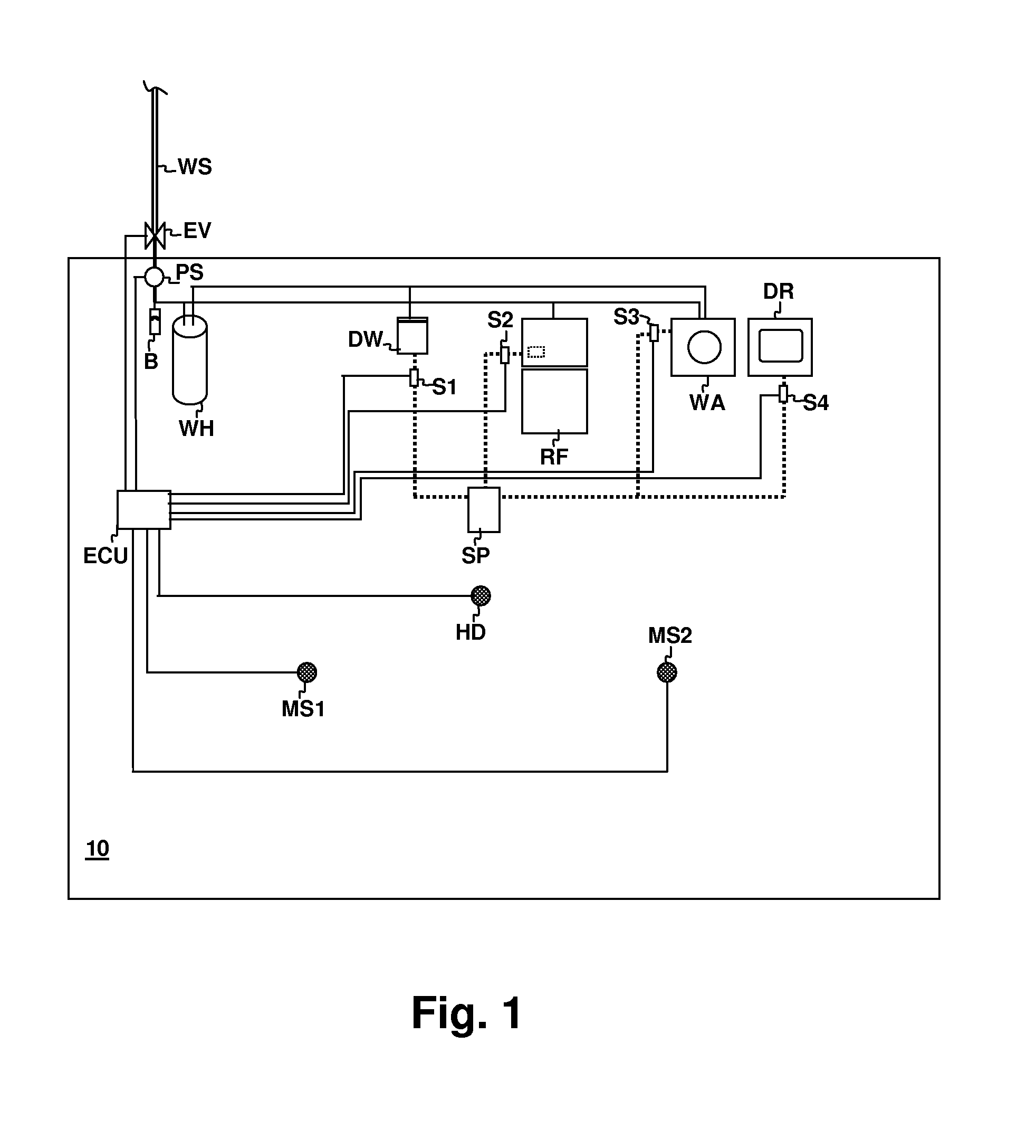
[0016]Referring now to FIG. 1, a residential building 10, is shown that incorporates a system in accordance with an embodiment of the present invention. Building 10, ...


PUM


Abstract

A methods and system detecting water system leaks provides detecting of water leakage having very low flows. Very low flow leaks are detected by detecting drops in a building water system pressure when the water supply source is disabled. The water system is disabled by an electrically controllable valve, which may be turned off in response to a motion detector that detects that no human activity is present in the building. The rate of pressure drop is used to determine the magnitude of the leak, and multiple thresholds can be used to detect slow leaks versus more serious leaks. A humidity detector may also be incorporated in the system to detect abnormal humidity conditions and shut the electrically controllable valve in response. Appliance current consumption can be detected and used to override motion-sensor based shut-off of the valve, so that water-consuming appliances can continue to operate.

Description

CROSS-REFERENCE TO RELATED APPLICATIONS[0001]The present U.S. Patent Application is related to co-pending U.S. patent application Ser. No. 11 / 734,714 entitled “METHOD AND SYSTEM FOR RELIABLY DETECTING STRUCTURE AND WATER SYSTEM LEAKS” filed on Apr. 12, 2007. The above-referenced U.S. Patent Application is incorporated herein by reference.BACKGROUND OF THE INVENTION[0002]1. Field of the Invention[0003]The present invention relates generally to building protection systems, and more specifically, to a system for controlling a household water supply.[0004]2. Background of the Invention[0005]Prevention of loss due to water damage in both residential and commercial locations has long been a concern and have been addressed in various manners in the past, the simplest of which are sump pumps or floor water presence detector. More recently, mold damage and other damage due to humidity has become a concern, in part, because health risks due to the presence of airborne “black mold” spores and ...

Claims


Application Information

Patent Timeline
Patent Type & Authority Applications(United States)
IPC IPC(8): E03B7/07
CPCE03B7/071G01M3/2815Y10T137/6969Y10T137/0777Y10T137/0396Y10T137/86485Y02A20/15
Inventor FORD, MICHAEL BRENT
Owner FORD MICHAEL BRENT
Why Eureka
Try Eureka