
Sipe blade and tire molded using the same

Active Publication Date: 2008-10-16
TOYO TIRE & RUBBER CO LTD
View PDF5 Cites 10 Cited by
  • Summary
  • Abstract
  • Description
  • Claims
  • Application Information

AI Technical Summary

Benefits of technology

[0007]The present invention has been proposed in view of the above circumstances. It is an object of the present invention to provide a sipe blade free from bending and / or breakage while vulcanizing processing of a tire and capable of preventing irregular wear such as river wear from being generated on the tire due to the formed sipe, and to provide a tire molded using the sipe blade.
[0009]In the sipe blade according to the present invention, the thickness of the front-end portion is larger than the smallest thickness in the portion between the front-end portion and the connection-end portion, and the thickness of the connection-end portion is the largest in the portion between the front-end portion and the connection-end portion. Therefore, the portion having the smallest thickness resides in neither the front-end portion nor the connection-end portion. The strength of the connection-end portion, where the stress tends to converge when the tire is removed from the mold after the vulcanizing processing, is increased. Accordingly, the blade is appropriately prevented from being bent or broken. Also, the connection-end portion has the largest thickness. With this arrangement, the land portion is prevented from forming a sharp angle near the open end of the formed sipe, thereby generation of the river wear is effectively prevented.
[0010]In the sipe blade according to the present invention, the thinnest portion having the smallest thickness is preferably continuous to the connection-end portion being interposed by a rounded surface having an arc-like shape. With this arrangement, the stress convergence on the connection-end portion is effectively suppressed, and thus the blade can be effectively prevented from being bent or broken.
[0012]In the tire according to the present invention, the width at the closed end of the sipe is larger than the smallest width in the portion between the closed end and the open end. Therefore, the stress convergence at the closed end is suppressed and crack resistance can be increased. Further, the width at the open end of the sipe is the largest in the portion between the closed end and the open end. Therefore, the land portion is prevented from forming a sharp angle near the open end, and thus irregular wear such as river wear is prevented. Also, since the configuration of the sipe blade for forming the sipe is as described above, the blade is prevented from being bent or broken while performing the vulcanizing processing.
[0013]In the tire according to the present invention, the narrowest portion having the smallest width is preferably continuous to the open end being interposed by a rounded surface having an arc-like shape. With this arrangement, crack (plucked-out) in the land portion near the open end causing the river wear is effectively prevented, and thus irregular wear is appropriately prevented.

Problems solved by technology

As a result, heel and toe wear may be generated thereon.
Therefore, there may occur such a problem that when a bending stress acts on the blade while removing the tire from the mold after the vulcanizing processing, a portion of the blade connected to the rib may function as a fulcrum of a bending deformation, and stress may converge to the connection portion causing a bending, breakage or damage.
However, in the case of such a tire, the thickness of the blade for forming the sipe is thin at the portion connected to the rib, while thick at the front-end portion.
Therefore, a large stress converges at the connection portion, and the blade tends to be bent or broken.
Moreover, there is a problem that the land portion tends to form a sharp angle near the open end of the sipe causing irregular wear such as river wear on the tread surface.

Method used


Image

  • Sipe blade and tire molded using the same
  • Sipe blade and tire molded using the same
  • Sipe blade and tire molded using the same

Examples


examples

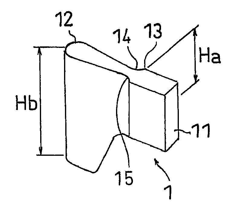
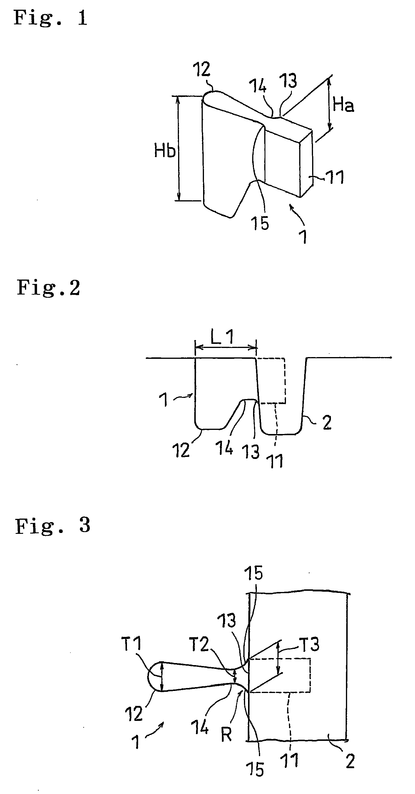
[0040]In order to demonstrate the arrangement and effect of the present invention, tires were subjected to vulcanizing processing using the above-described blades and the blades were checked for deforms thereon. As for the blades, the following were prepared. That is, examples having the configuration illustrated in FIGS. 1 to 3; and comparative examples having a configuration illustrated in FIG. 8, the thickness of which was the smallest at a portion connected with the rib. The dimensions of the examples are listed in the example 3 of the table 1. The dimensions of the comparative examples were T2=T3=0.5 mm. The comparative examples were identical to the examples excepting a point that round surface was not formed. In both of the examples and the comparative examples, the blade length was 11 mm, the material of the blade was SUS304, distance between the disposed blades was 5 mm, the material of the rib was AC7A, and the depth of the rib was 14 mm.

[0041]1,000 tires for each were sub...


PUM

PropertyMeasurementUnit
Lengthaaaaaaaaaa
Widthaaaaaaaaaa
Thicknessaaaaaaaaaa

Abstract

A sipe blade for forming a sipe with one end opened and the other end closed in a land portion on a tread surface of a tire includes a front-end portion that forms the closed end of the sipe and a connection-end portion that forms the open end of the sipe being connected to a rib that forms a groove. A first thickness of the front-end portion is larger than a second thickness of a thinnest portion. A third thickness of the connection-end portion is 3 mm or less and is the largest thickness in a portion between the front-end portion and the connection-end portion, and the ratio of the third thickness with respect to the second thickness; i.e., the third thickness / the second thickness is 1.2 to 3.0.

Description

BACKGROUND OF THE INVENTION[0001]1. Field of the Invention[0002]The present invention relates to a sipe blade for forming a sipe with one end opened and the other end closed in a land portion on a tread surface of a tire, and to a tire molded using the sipe blade.[0003]2. Description of the Related Art[0004]Conventionally, a heavy load pneumatic tire is formed with a plurality of cuts called sipes in a land portion such as a block or rib formed in a tread surface of the tire in order to increase the braking performance and driving performance as well as to reduce irregular wear of the tire. Particularly, the following sipes are effective for reducing the stiffness of the land portion; i.e., both-side-open sipe with open ends at both side walls of a land portion; and one-side-open sipe with one end opened and the other end closed. In the both-side-open sipe, since a land portion is divided into a plurality of small blocks, the stiffness of the land portion may be reduced too much. As...

Claims


Application Information

Patent Timeline
IPC IPC(8): B60C11/12B29C59/02
CPCB29C37/0057B29D2030/0613B29L2030/00B60C11/12B60C11/1281Y10S152/03
Inventor OHARA, MASAAKI
Owner TOYO TIRE & RUBBER CO LTD
Features
  • Generate Ideas
  • Intellectual Property
  • Life Sciences
  • Materials
  • Tech Scout
  • Unparalleled Data Quality
  • Higher Quality Content
  • 60% Fewer Hallucinations
Learn More