RFID hard case device and method of manufacture

a hard case and hard case technology, applied in the field of waste and recycling containers, can solve the problems of inoperable devices, container becomes unusable, and unsuccessful attempts to implement these approaches, and achieve the effect of reducing potential harm

Inactive Publication Date: 2008-10-16
CASCADE ENG
View PDF27 Cites 19 Cited by
  • Summary
  • Abstract
  • Description
  • Claims
  • Application Information

AI Technical Summary

Benefits of technology

[0004]The aforementioned problems are overcome by the present invention wherein an RFID device is protectively enclosed in a case that is designed to be incorporated into a waste / recycling container in structure and processes that reduce potential harm to the RFID device.
[0005]In one embodiment, the case is relatively flat and includes relatively large front and rear surfaces. The surfaces define a wedge shape for the case in cross section. The RFID device is protectively enclosed within the case to withstand in-molding as described below. In a second embodiment, the waste container includes the in-molded case. At least a portion of both the front surface and the rear surface are not covered by plastic, so that the case is protected from the pressures and temperatures of the injection molding process.
[0008]The present invention enables attachment of an RFID device to a waste / recycling container without destroying the functionality of the device during the attachment process. The wedge shape of the case and corresponding wedge shape of the mold pocket enables a secure fit within the mold that prevents the flow of plastic over the front and rear surfaces of the case—protecting the RFID device from the heat and pressure of the molten thermoplastic. The protrusions on the case further enable retrofitting of the case to containers with or without an in-molded case.

Problems solved by technology

Unfortunately, attempts at implementing this approach have been unsuccessful and at best inconsistent because of the temperatures and pressures associated with injection molding.
Even when the device is encapsulated in a protective shell, the heat and pressure of plastic flowing over the shell can render the device inoperable.
The container therefore becomes unusable.

Method used


Image

  • RFID hard case device and method of manufacture
  • RFID hard case device and method of manufacture
  • RFID hard case device and method of manufacture

Examples


Embodiment Construction

[0017]I. Overview

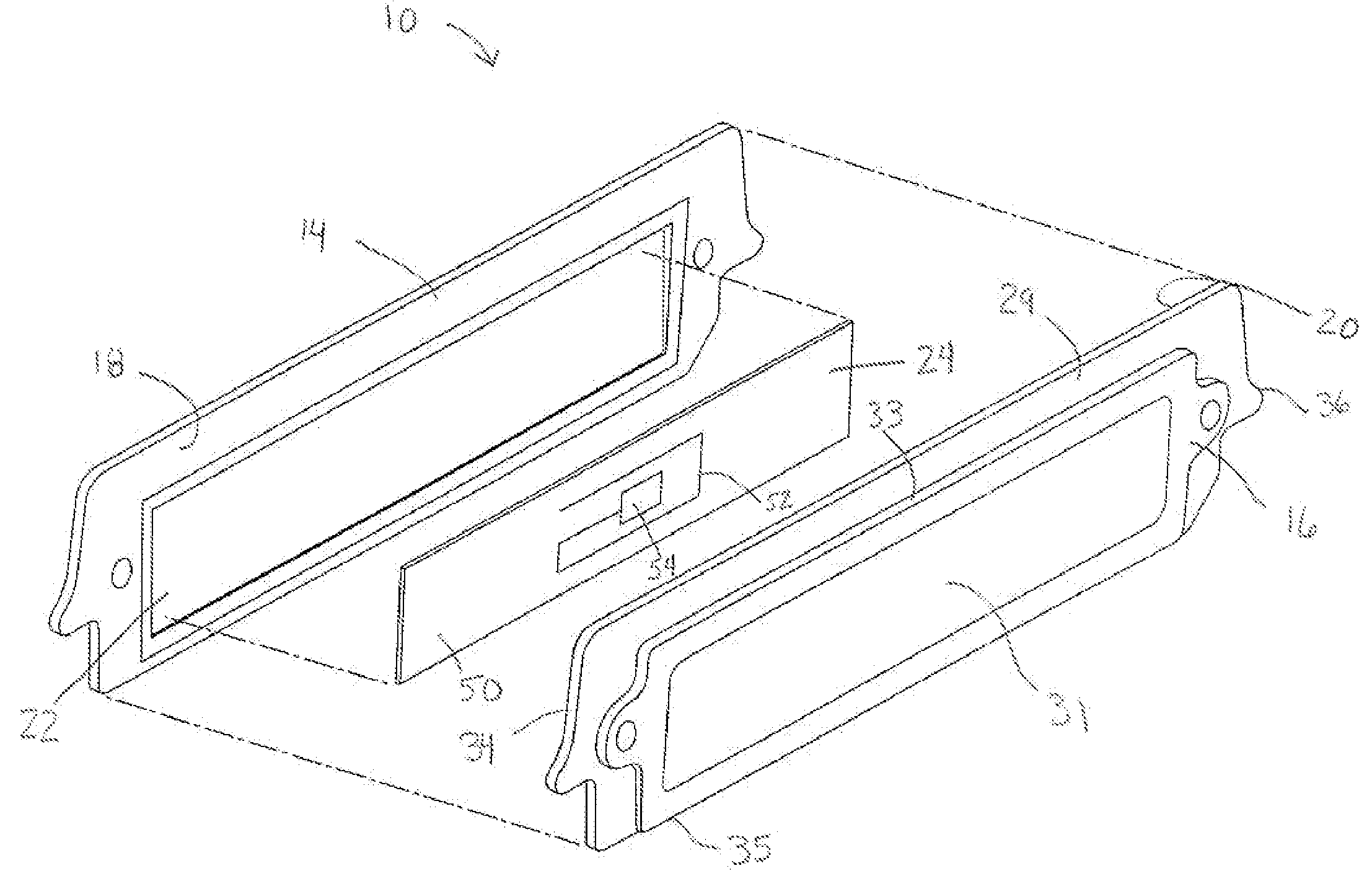
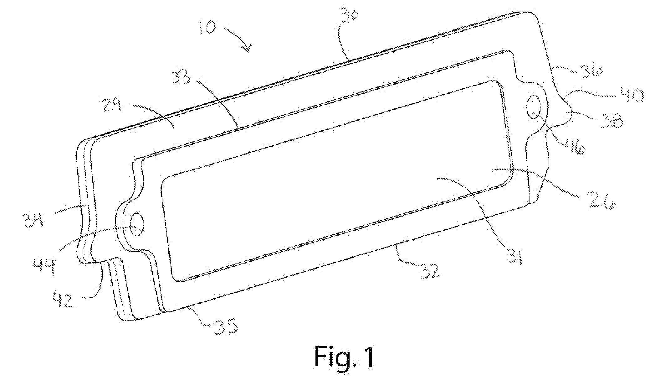
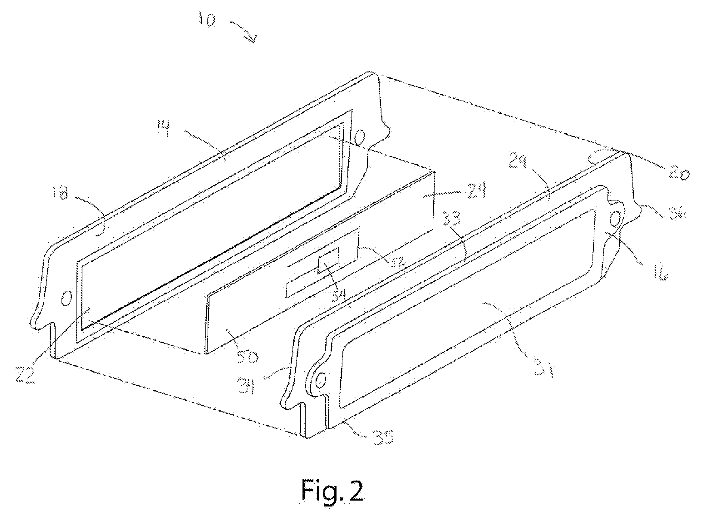
[0018]An RFID hard case according to one embodiment of the present invention is shown in FIG. 1 and generally designated 10. In one embodiment, shown in FIG. 5, the RFID hard case 10 is designed to be molded into a plastic item, such as a waste / recycling container 12. In one embodiment, the RFID hard case 10 is also designed to snap-fit into a portion of the waste / recycling container 12. For purposes of illustration, the invention will be described in connection with a waste / recycling container. It should be appreciated, however, that the construction and method described herein could be applied to attach an RFID device to a wide variety of plastic items.

[0019]II. Structure

[0020]The case 10 is typically injection molded plastic, but may be formed from a variety of materials. In one embodiment, the case 10 includes a first half 14 and a second half 16. The halves 14 and 16 are generally identical and include interior surfaces 18, 20 respectively that each define a ca...


PUM

PropertyMeasurementUnit
wedge shapeaaaaaaaaaa
moldingaaaaaaaaaa
frequencyaaaaaaaaaa

Abstract

An RFID enabled waste / recycling container includes a molded plastic body; and a case containing an RFID device. The case includes a front surface and a rear surface defining a wedge-shape. The case is in-molded with the plastic body such that a substantial portion of the front surface and the rear surface are exposed. In another embodiment, the case is also designed to snap-fit to a waste / recycling container.

Description

BACKGROUND OF THE INVENTION[0001]The present invention relates to waste and recycling containers, and more particularly to waste and recycling containers including radio frequency identification (RFID) devices.[0002]With increasing frequency, waste and recycling containers are being equipped with radio frequency identification (RFID) devices. An RFID device enables the container to be uniquely identified or associated with a customer or pick-up address. The RFID device typically is read during emptying of the container by an RFID reader within the equipment for lifting and / or weighing the container. Where charges are based on the weight of the waste (or where rebates, rewards, or other benefits are provided based on the weight of the recyclable materials), the RFID device enables weight information to be accurately associated with a customer or a pick-up address to enable accurate and reliable customer billing.[0003]One way of equipping a plastic waste container with an RFID device ...

Claims


Application Information

Patent Timeline
Patent Type & Authority Applications(United States)
IPC IPC(8): B29C45/14
CPCB29C45/14065B29C45/14836B29C2045/14844B29C2045/14852B65F1/1484B29L2031/7134
Inventor MISNER, JOHN E.PARKER, BRIAN G.
Owner CASCADE ENG
Why Eureka
Try Eureka