
Device and Method for Calibrating the Center Point of a Tool Mounted on a Robot by Means of a Camera

Inactive Publication Date: 2008-10-16
ABB (SCHWEIZ) AG
View PDF7 Cites 52 Cited by
  • Summary
  • Abstract
  • Description
  • Claims
  • Application Information

AI Technical Summary

Benefits of technology

[0015]The advantage achieved by using a camera is that all positions along the contour of the tool are obtained on one and the same measurement occasion. Measurement using a camera means that the position of the tool is obtained in the system of coordinates of the camera. The position of the camera in relation to the system of coordinates of the robot is not known. One advantage achieved is that a faster calibration of the tool may be performed. Another advantage is that a higher repetition accuracy and better precision are obtained, which leads to higher operating availability of the robot.
[0016]One further advantage achieved is that reorientation about the axis of the camera lens and the axis of the tool means that the shape of the tool is not changed, which makes it easier for the image-processing unit to locate the TCP in a simple manner.
[0017]Still another advantage achieved is that it is considerably less expensive to use a camera for determining position compared with using, for example, laser or IR.
[0018]Yet another advantage achieved is that it is possible to carry out the calibration without an operator having to be involved in the work.
[0020]According to another embodiment of the invention, the device comprises a light source arranged such that the location of the tool is between the light source and the camera. The advantage obtained by this is that also tools that emit reflexes, which normally entails problems since these may fool the image-processing unit, may be determined, in a simple manner, with respect to their position with the aid of the image-processing unit.

Problems solved by technology

The methods applied today for TCP calibration are both impractical and slow.
The disadvantage of using the above-mentioned solutions is that it takes a relatively long time (5-10 minutes) to use light beams to carry out each calibration.
It is also known to carry out TCP calibration by manually performing measurement at at least four points on the tool, but also this method is unpractical and slow.
The disadvantage of this method is that it is expensive and slow.
In addition, the accuracy obtained using this type of measurement is, in many cases, unnecessarily high.

Method used


Image

  • Device and Method for Calibrating the Center Point of a Tool Mounted on a Robot by Means of a Camera
  • Device and Method for Calibrating the Center Point of a Tool Mounted on a Robot by Means of a Camera
  • Device and Method for Calibrating the Center Point of a Tool Mounted on a Robot by Means of a Camera

Examples


Embodiment Construction

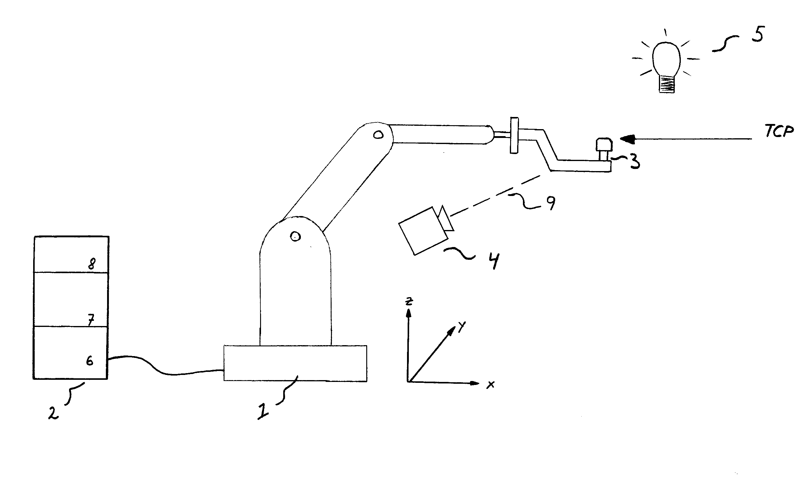
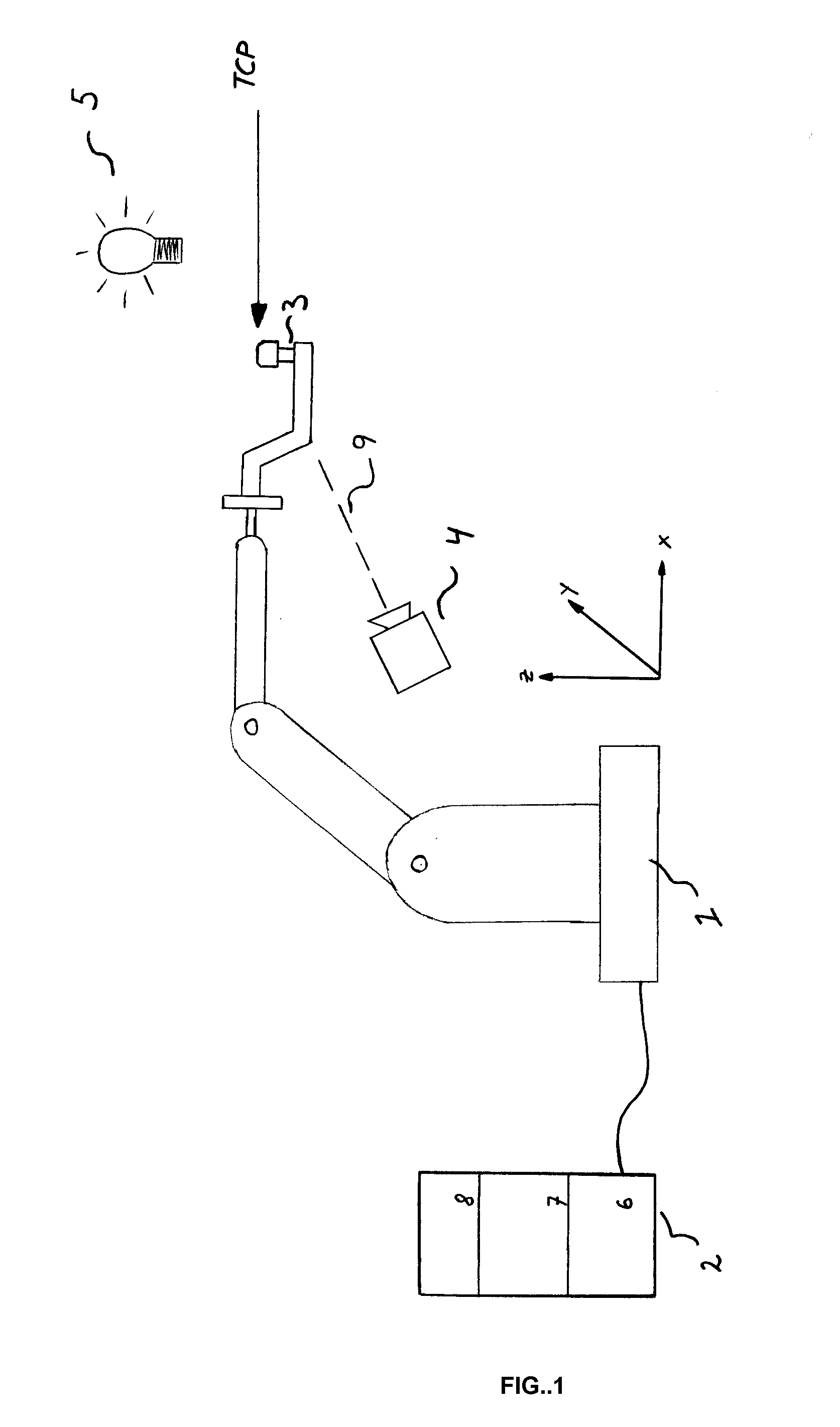
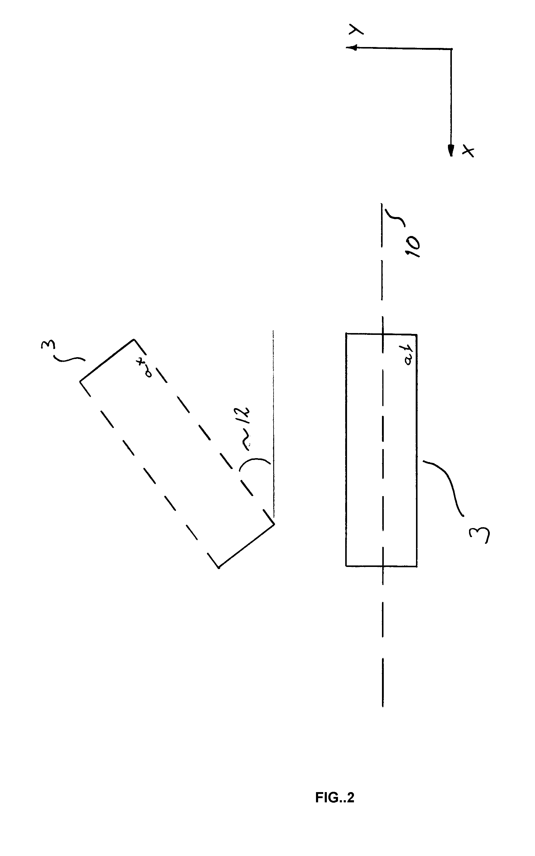
[0025]FIG. 1 shows a robot cell comprising a robot 1 with a control unit 2 connected thereto and a tool 3 connected to the robot. The control unit 2 comprises, inter alia, at least one processor and at least one memory unit. The control unit 2 stores the control program of the robot and an algorithm that controls the TCP calibration. The control unit 2 also stores the position of the desired TCP as well as geometrical information about the tool 3 in different predetermined positions. Accommodated in the control unit 2 is an image-processing unit 6 containing an image-processing algorithm. The image-processing algorithm may be any image-processing algorithm that is useful according to the state of the art. Furthermore, the control unit 2 comprises a calculation module 7 containing an algorithm intended to calculate the TCP, and the control unit also comprises a control module 8 adapted to calculate the corrective movements of the robot. According to the invention, a camera 4 is arran...


PUM


Abstract

A device and a method for tool center point calibration of an industrial robot. The device is intended to calibrate an industrial robot with respect to a tool mounted on the robot. The device includes a camera designed to take a plurality of images of at least part of the robot tool for a plurality of different tool orientations, an image-processing unit designed to determine the positions of the robot tool in the orientations based on the images, a calculation module adapted to calculate the position of the center point of the robot tool, based on the determined positions, and a control module adapted to calculate the corrective movements of the robot.

Description

TECHNICAL FIELD[0001]The present invention relates to a device and a method for tool centre point calibration, hereinafter referred to as TCP calibration, of an industrial robot. The device is intended to calibrate an industrial robot with respect to a tool mounted on the robotBACKGROUND ART[0002]Carrying out accurate measurement of the centre point of a tool mounted on an industrial robot is of the utmost importance for the robot to be able to perform its programmed work tasks correctly. The methods applied today for TCP calibration are both impractical and slow. This particularly applies to the case where it is necessary to use an operator for carrying out the calibration. An industrial robot usually has 4-6 axes of rotation. The last link in the chain may consist of a toolholder. Different tools are used depending on the field of application and may be, for example, a gripper, a glue gun or a welding tool. The position for this tool relative to the base coordinate system of the r...

Claims


Application Information

Patent Timeline
IPC IPC(8): B25J9/16
CPCB25J9/1692B25J9/1697G05B2219/39394G05B2219/40607G05B2219/40611
Inventor LUNDBERG, IVANDURINDER, NIKLASBROGARDH, TORGNY
Owner ABB (SCHWEIZ) AG
Learn More