
Device select system for multi-device electronic system

a select system and electronic system technology, applied in the direction of head disposition, track selection/addressing details, pulse technique, etc., can solve the problems of increasing complexity and cost of cables, affecting the bandwidth of actuators, and difficult cable routing for freedom of movemen

Inactive Publication Date: 2008-10-16
GLOBALFOUNDRIES INC
View PDF19 Cites 11 Cited by
  • Summary
  • Abstract
  • Description
  • Claims
  • Application Information

AI Technical Summary

Benefits of technology

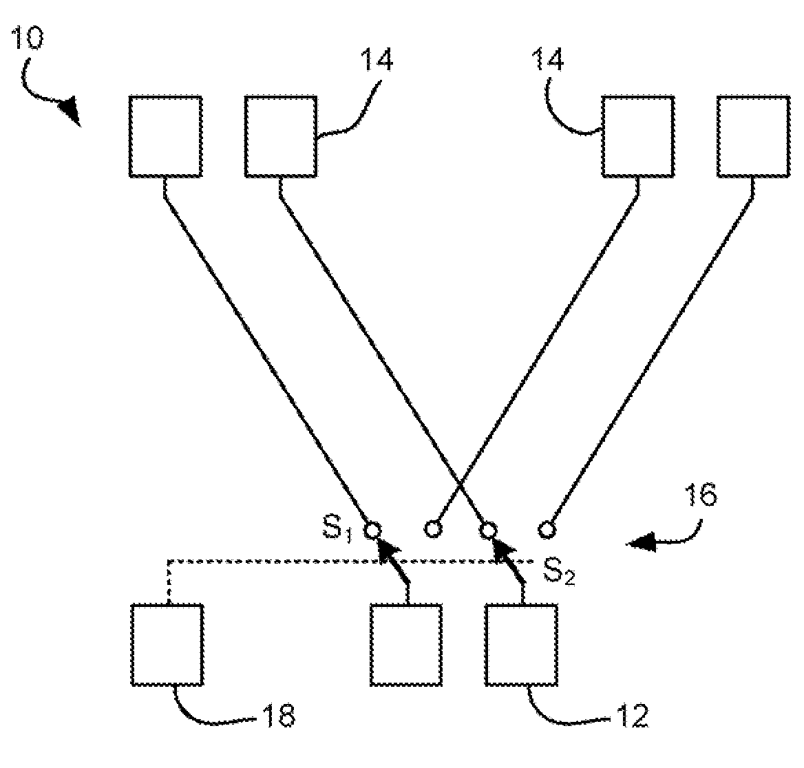
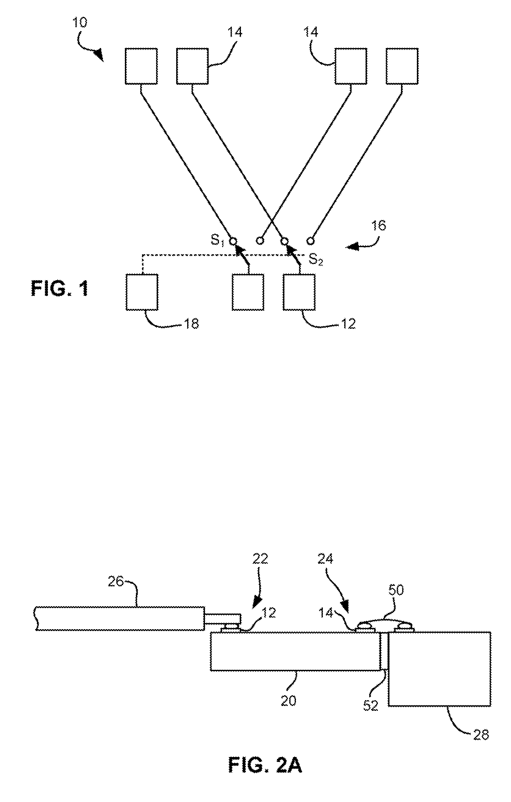
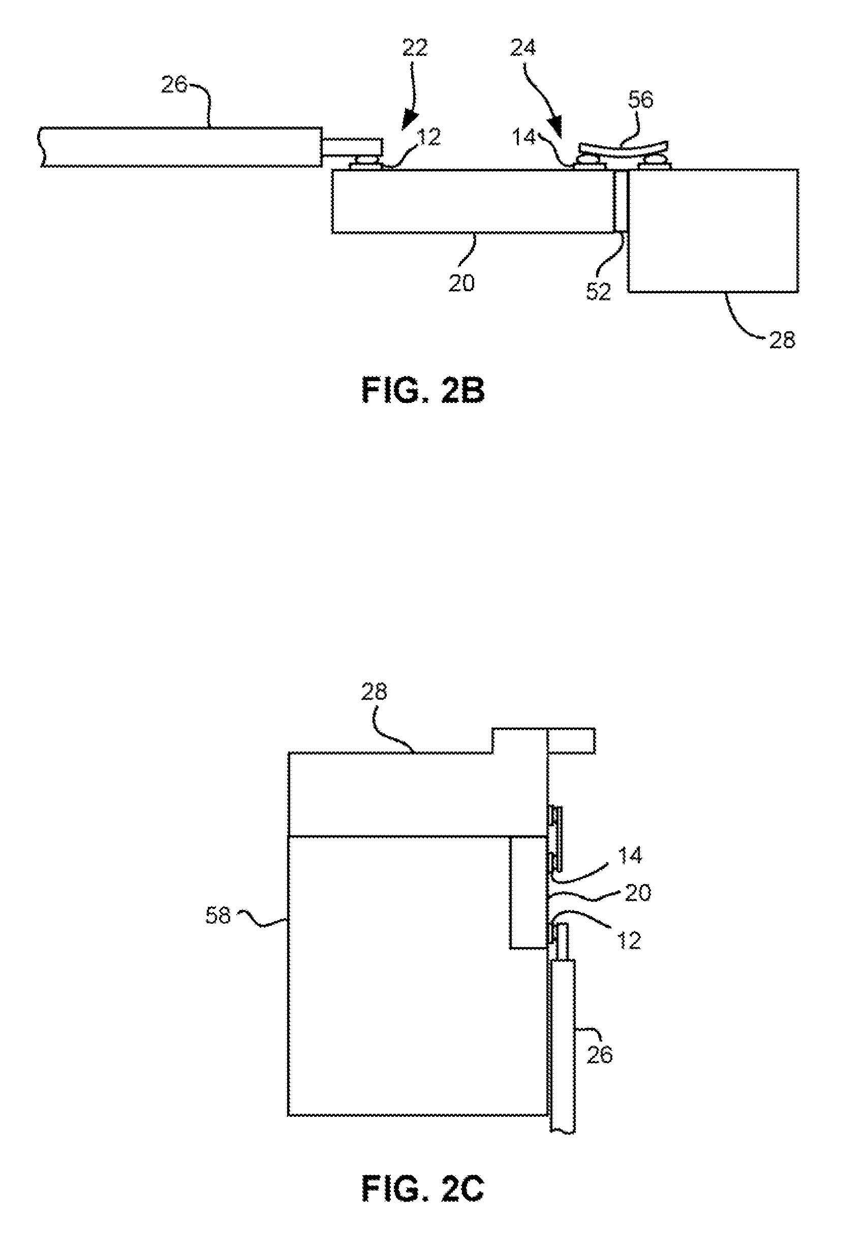
The patent describes a device select system and a magnetic head for use in a tape drive system. The device select system includes an array of first electrical contacts and an array of second electrical contacts. The first electrical contacts are associated with at least two of the second electrical contacts. A select mechanism is used to selectively place each first electrical contact in electrical communication with one of the associated second electrical contacts. This allows for the efficient coupling of the first electrical contacts to the second electrical contacts. The magnetic head includes an array of first electrical contacts and a plurality of transducers. The first electrical contacts are associated with at least two of the transducers, and the select mechanism is used to selectively place each first electrical contact in electrical communication with one of the associated transducers. This allows for the efficient coupling of the first electrical contacts to the transducers. The technical effects of this invention include improved signal quality and reliability in the tape drive system.

Problems solved by technology

One problem that arises is that cables tend to get more complex and costly as the number of devices in the head and therefore the number of leads in the cable, increases.
Further, cables tend to get wider, and thus stiffer and more massive as the number of leads increases, which in turn can negatively affect actuator bandwidth and make cable routing for freedom of motion more difficult.
Generally, shrinking the dimensions of the leads in the cable is not all option, as DC resistance and AC impedance would also change undesirably.
Current technology fails to address tape head cabling problems that will be posed by bourgeoning I / O needs for future multi-track, multi-format or multi-function tape heads.

Method used


Image

  • Device select system for multi-device electronic system
  • Device select system for multi-device electronic system
  • Device select system for multi-device electronic system

Examples


Embodiment Construction

[0037]The following description is the best mode presently contemplated for carrying out the present invention. This description is made for the purpose of illustrating the general principles of the present invention and is not meant to limit the inventive concepts claimed herein. Further, particular features described herein can be used in combination on with other described features in each of the various possible combinations and permutations.

[0038]In the drawings, like and equivalent elements are numbered the same throughout the various figures.

[0039]The embodiments described below disclose a new device select system that allows selective creation of electrical connections between electrical contacts for such things as selecting particular groups of transducers and not others. The system may be fabricated as a standalone unit, or integrated into an intermediate or final device. In particularly preferred approaches directed to tape-based data storage systems, the device select sy...


PUM


Abstract

A device select system according to one embodiment includes an array of first electrical contacts adapted for coupling to a cable; an array of second electrical contacts adapted for coupling to an array of transducers, there being more second electrical contacts than first electrical contacts each of the first electrical contacts being associated with at least two of the second electrical contacts; and a select mechanism for selectively placing each of the first electrical contacts in electrical communication with one of the second electrical contacts associated therewith.

Description

FIELD OF THE INVENTION [0001]The present invention relates to magnetic storage system components, and more particularly, this invention relates to a device select system for selecting devices on a magnetic head.BACKGROUND OF THE INVENTION[0002]Business, science and entertainment applications depend upon computers to process and record data, often with large volumes of the data being stored or transferred to nonvolatile storage media, such as magnetic discs, magnetic tape cartridges, optical disk cartridges, floppy diskettes, or optical diskettes. Typically magnetic tape is the most economical means of storing or archiving the data. Storage technology is continually pushed to increase storage capacity and storage reliability. Improvement in data storage densities in magnetic storage media, for example, has resulted from improved medium materials, improved error correction techniques and decreased areal bit sizes. The data capacity of half-inch magnetic tape, for example, is now measu...

Claims


Application Information

Patent Timeline
Patent Type & Authority Applications(United States)
IPC IPC(8): H03K17/56
CPCH03K17/002G11B5/4893G11B5/4984G11B5/78G11B2220/90
Inventor BISKEBORN, ROBERT GLENNGOLDBLATT, RONALD DEAN
Owner GLOBALFOUNDRIES INC
Learn More