Architecture For Rfid Tag Reader/Writer

a technology of tag reader and tag writer, which is applied in the direction of transmission, subscriber station connection selection arrangement, indirect connection of subscriber, etc., can solve the problems of requiring an additional frequency synthesizer, requiring two frequency synthesizers, and significant expense, so as to achieve less power, less ic real estate, and good image rejection

Inactive Publication Date: 2008-10-16
AGENCY FOR SCI TECH & RES +1
View PDF0 Cites 6 Cited by
  • Summary
  • Abstract
  • Description
  • Claims
  • Application Information

AI Technical Summary

Benefits of technology

[0007]The present invention provides an improved RFID transceiver architecture which exhibits good image rejection while using a single frequency source common to the transceiver's transmitting and receiving channels. As a result, the RFID transceiver operates on less power and requires less IC real estate.

Problems solved by technology

The difficulties with such a direct conversion receiver are well known and include dynamically varying DC offset level, I / Q mismatch, and erroneous baseband signals generated by the cross-modulation of the RF signal (i.e., the received RFID signal) and the LO signal (the internally generated reference signal).
The superheterodyne mixing approach provides some relief to the aforementioned obstacles, but at significant expense.
The disadvantage of such a system is that it creates a requirement for an additional frequency synthesizer, as the transmitting and receiving channels typically require their own frequency source in this design.
The presence of both frequency synthesizers decreases available chip real estate and drains much needed power.

Method used


Image

  • Architecture For Rfid Tag Reader/Writer
  • Architecture For Rfid Tag Reader/Writer
  • Architecture For Rfid Tag Reader/Writer

Examples


Embodiment Construction

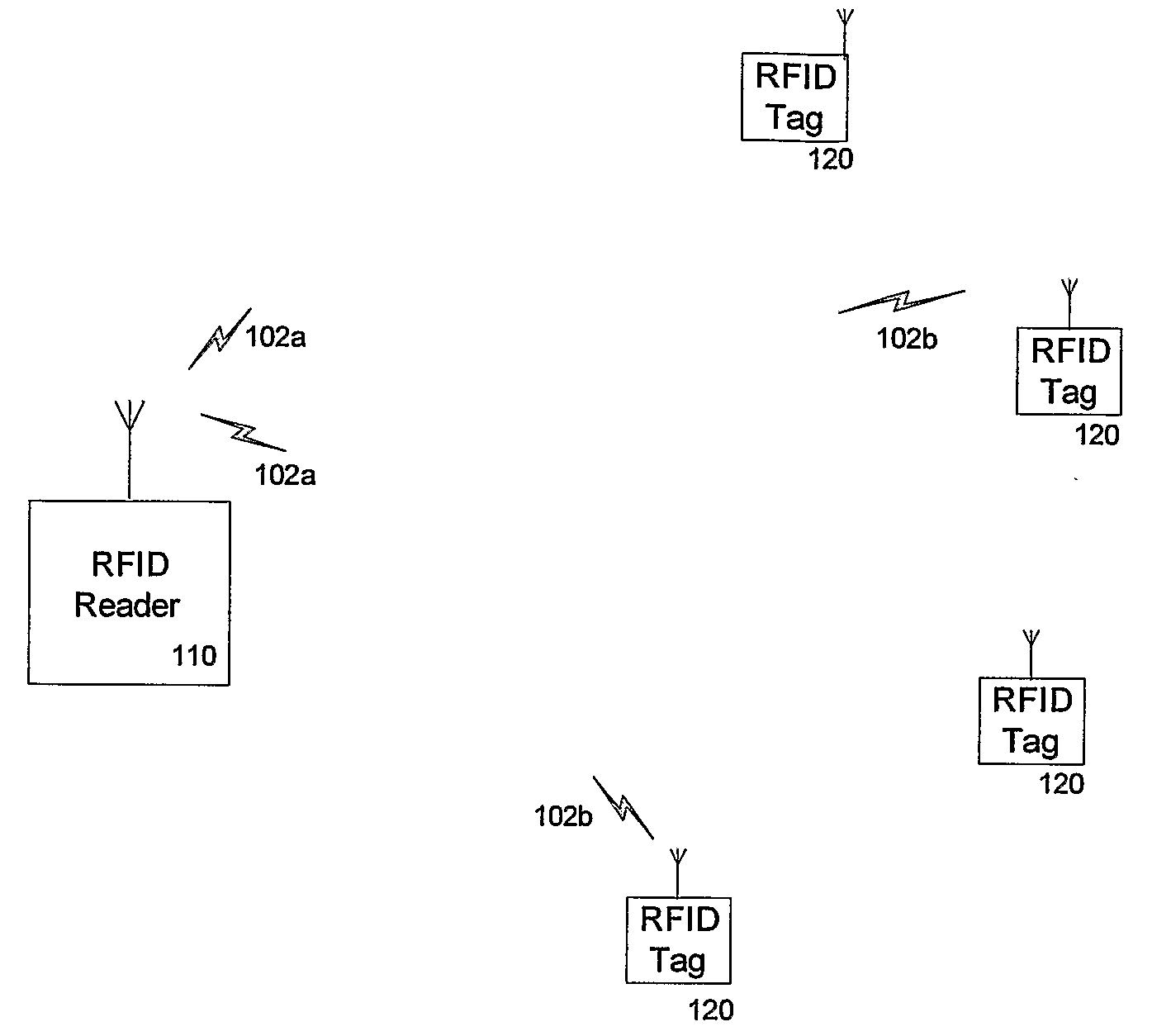
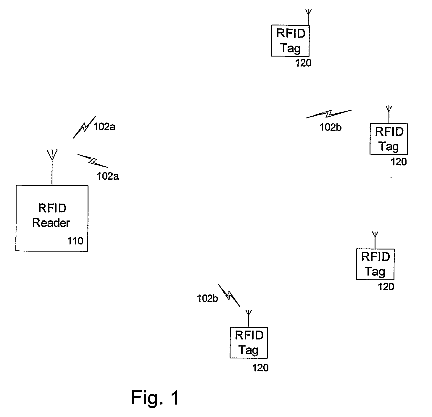
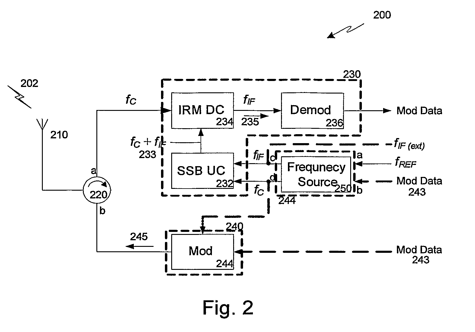
[0013]FIG. 2 illustrates a block diagram of a RFID transceiver in accordance with one embodiment of the present invention. The transceiver 200 includes an antenna 210, a circulator 220, an RFID receiving channel 230, an RFID transmitting channel 240, and a common frequency source 250. The RFID receiving channel 230 includes a single sideband upconverting mixer 232, an image rejection down converting mixer 234, and a demodulator 236. The RFID transmitting channel 240 includes a modulator 244, which in a particular embodiment (indicated by the dashed lines) includes the common frequency source.

[0014]The antenna 210 is operable to transmit RFID signal 202, which may be in the form of amplitude shift-keyed (ASK), on-off keyed (OOK), frequency shift-keyed (FSK) formatted signals and to receive RFID signal 202, which may be in the form of amplitude shift-keyed (ASK), on-off keyed (OOK), frequency shift-keyed (FSK) or phase shift-keyed (PSK) formatted signals. Circulator 220 provides isola...


PUM


Abstract

An RFID transceiver (200) includes a common frequency source (50), a receiving channel (230) and a transmitting channel (240). The common frequency source (250) is configured to provide a predefined intermediate frequency signal fIF, and a predefined carrier frequency signal fc. The RFID receiving channel (230) includes an upconverting mixer (232) having a first input coupled to receive the predefined intermediate frequency signal fIF, a second input coupled to receive the predefined carrier frequency signal fc, and an output, the upconverting mixer (232) operable to produce an upconverted signal at a frequency defined by fc±fIF. The RFID receiving channel (230) further includes an image rejection downconverting mixer (234) having a first input coupled to receive an RFID signal having a carrier frequency substantially at the predefined carrier frequency fc, a second input coupled to receive the upconverted signal, and an output, the image rejection downconverting mixer (234) operable to produce an output a downconverted signal at substantially the predefined intermediate frequency fIF. The RFID transmitting channel (240) includes a modulator (244) operable to modulate modulation data onto the predefined carrier frequency signal fc.

Description

BACKGROUND[0001]The present invention relates to radio frequency identification circuitry, and more particularly, to transceiver architectures for radio frequency identification systems.[0002]Radio frequency identification (RFID) systems are wireless telemetry systems, whereby a transponder or RFID “tag” communicates information to an interrogation transceiver or RFID “reader.” The information provided by the RFID tag may be location information, the tag's identity, or other data. Continued improvements in circuit miniaturization have resulted in very small RFID tags that can be unobtrusively placed on an item which is to provide the aforementioned telemetry. The RFID tag communicates the information to the RFID reader when interrogated, or otherwise activated to do so.[0003]FIG. 1 illustrates a simplified block diagram of an RFID system. The system includes an RFID reader 110 and one or more RFID tags 120, between which RFID signals 102 are communicated. The RFID reader 110 operate...

Claims


Application Information

Patent Timeline
Patent Type & Authority Applications(United States)
IPC IPC(8): H04Q5/22
CPCG06K7/0008
Inventor KHANNUR, PRADEEP B.WONG, SHENG JAUAJJIKUTTIRA, ARUNA B.ZHENG, JIA JUN
Owner AGENCY FOR SCI TECH & RES
Why Eureka
Try Eureka